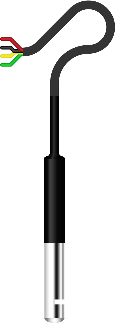
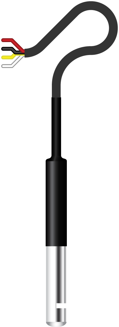
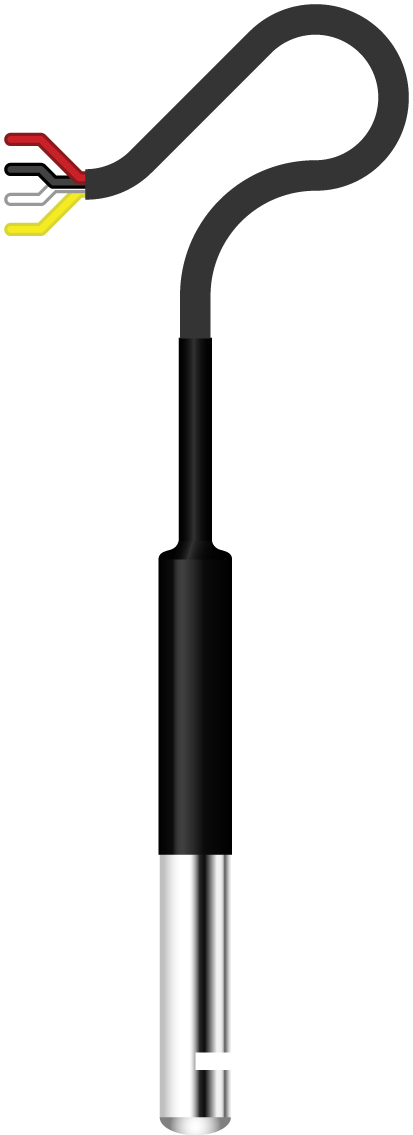
In creating a Fritzing part for an SHT40 probe sensor, I was confronted by a bit of a dilemma. All of the documentation associated with this probe indicated that the I2C SCL wire was yellow and the I2C SDA wire was green or white. The probe that I was supplied, however, had the wire colours reversed—the wire carrying the SDA signal was the yellow one, while the SCL signal wire was white.
So what was I to do in creating a Fritzing part? Should I use the wire colours as documented, or the wire colours on the probes that were supplied?
In the end, I created three versions—one with each possible colour for the SDA wire. It’s just a pedantic [breadboard illustration] thing, they are functionally identical—they all use the same PCB and Schematic views and the wire sequence, VCC GND SCL SDA, is the same in each version—it’s only the colours of the SCL and SDA wires [in the breadboard and icon images] that are different.
The version in use in a Fritzing document, if more than one is loaded, can be changed through the inspector.
.


