

I2C Communications

The I2C Bus
The Inter-Integrated Circuit (I2C) bus is a two-wire (Data + Clock) bus supported on Arduino processors by the Wire library. The processor pins used for the data (SDA) and clock (SCL) signals can generally be assigned to any GPIO pins that support both input and output functions (Note that some ESP32 pins, for example, are input-only pins and thus cannot be used in this context). In many cases, default GPIO pin assignments are defined, as SDA and SCL, in the pins_arduino.h file associated with a specific processor.
When using the Arduino IDE under macOS, the path to the pins_arduino.h files for Heltec for ESP32 devices is:
|
The pins_arduino.h files for other ESP32 boards can be found following a similar path under:
|
and for ESP8266 (ESP-12) devices:
|
When using the Arduino IDE under macOS, the pins_arduino.h files for CubeCell devices are located under the Arduino directory, which by default is at:
|
Bus Instantiation & Initialisation
The conventional instantiation of an I2C bus using the Wire library would take the form:
|
If using the default I2C bus GPIO pins, defined in the relevant pins_arduino.h file, the bus would then be initialised within the sketch setup() function:
|
The Wire library, however, includes default instantiations, Wire and Wire1, for two I2C buses:
|
so that these two entities can be used within a sketch without any need for explicit definition. Further, when initialising an I2C bus, if no pins are specified, default assignments defined in the relevant pins_arduino.h file are assumed. Accordingly, using the default Wire instantiation and the default SDA and SCL pin assignments, the above two-step instantiation/initialisation process would simplify to:
|
Nonetheless, any two GPIO pins that are appropriate for a given processor can be used for an I2C bus provided they are explicitly identified, in the begin() function, when initialising the bus.
Device Addressing
One of the fundamental features of bus communications is that they allow several devices to be connected to a processor through a single interface. There must then, of course, be some means of identifying the individual devices on the bus and in the case of the I2C bus this is a globally unique device address, although describing the addresses as globally unique is not entirely accurate.
Unlike the addressing generally used in networking, I2C device addresses are assigned more to device classes than individual devices. As such, for example, the series of Bosch BME atmospheric sensors all share just two I2C device addresses, 0x76 and 0x77. Where more than one address has been allocated to a class of devices, as in this example, the actual address used will generally be set through appropriate hardware configuration, sometimes fixed, sometimes configurable through jumpers or the like. Either way, whether there is just one or a range of assigned addresses, the number of similar devices that can be configured on a single I2C bus is thus limited.
The I2C addresses of devices currently discussed on this website are presented below for quick reference.
| Device | I2C Address |
|---|---|
| ADS1115 | 0x48 to 0x4B |
| AHT21 | 0x38 |
| AT24Cxx EEPROM | 0x50 to 0x57 |
| BME280 | 0x76 or 0x77 |
| BME680 | 0x77 or 0x76 |
| CCS811 | 0x5A or 0x5B |
| DS1307 | 0x68 |
| ENS160 | 0x52 or 0x53 |
| INA219 | 0x40 |
| MAX44009 | 0x4A |
| [SSD1306] OLED Display | 0x3C or 0x3D |
| PCF8574 | 0x20 to 0x27 |
| SHT4x | 0x44 to 0x46 |
| VEML6075 | 0x10 |
Where more than one address is listed, the default is usually the first listed in the table above. Alternate addresses can generally be set either through jumpers or by tying pins together on the respective modules.
Note the potential address conflict between AT24Cxx EEPROMs and the ENS160 sensor. This will be a problem if there is an attempt to use an ENS160 sensor module in the same configuration as an AT24C04, AT24C08 or AT24C16 EEPROM (see the following discussion on the subject of EEPROM addressing). A similar situation could arise attempting to use the ADS1115 ADC port expander with the MAX44009 ambient light sensor.
EEPROM Addressing
EEPROMs, certainly in the context of the Atmel AT24Cxx series of EEPROMs that I use in my applications, present an interesting case in the context of I2C device addressing. The curiosity in this case is probably as much to do with the EEPROM hardware as software because it relates to the way in which memory within the EEPROM is addressed.
This is necessarily a simplified explanation and the interested reader is encouraged to consult the relevant datasheet(s) for specific details—I have only used the AT24C01-16 and AT24C32-64 EEPROMs, but the larger ones are similar. The issue is that, for example, the internal address on the smaller EEPROMs (< 16K) is limited to just 8 bits, so that only 256 bytes are directly addressable. To manage this issue, EEPROMs of more than 2K bits (256 bytes), up to 16K, are effectively addressed in 256 byte blocks, each identified by a unique I2C device address, starting with 0x50. It can be a little confusing for the uninitiated when an I2C bus scan of an EEPROM appears to show more than a single device.
|
Serial Monitor output from an I2C scan of an AT24C08 EEPROM
EEPROM internal addressing is discused in more detail elsewhere on this website.
Multiple I2C Buses
As already noted, the Wire library includes default instantiations for two I2C buses, Wire and Wire1. As also noted above, the user also has the option of creating their own named instance of either bus.
|
Indeed, all of the processors discussed on this site, with the exception of the Arduino Pro Mini, support the definition of two independent I2C buses—the Arduino Pro Mini only supports a single I2C bus.
There are situations where this ability to define multiple I2C buses is very useful, if not critically important. Having noted that two identical I2C devices will generally share the same I2C address, for example, and can thus not be configured on the same I2C bus, the solution then, when two are required, is then to configure them on separate buses.
There are a couple of other situations, involving Heltec boards in particular, that make use of this capability.
Heltec Boards with OLED Displays
I have encountered several issues with the way Heltec manages the on-board display on some of their dev-boards. There is a naming conflict when using the LoRaWan_APP library, the curious decision to no longer break out the pins used by the I2C bus to which the on-board display is connected and the decision not to include, in their own display support libraries, the ability to specify on which logical I2C bus the display should be configured.
Note that libraries that support the SSD1306 and SH1107 OLED displays used on Heltec boards generally load the Wire library automatically and, by default, internally create the I2C bus instance required to support the relevant OLED display.
The Display Entity Name Conflict
The Heltec LoRaWan_APP library goes one step further and internally instantiates a display entity for the purpose of reporting the status of any subsequently defined LoRaWAN connection. The first problem here is that the instance is created when the library header file is loaded, not only if and when it is actually required. The second problem is that the Heltec designers decided to name this instance display, probably the most commonly used name when using the OLED display in a user sketch. The result is that, even if the user's sketch isn't using LoRaWAN—it could, as is generally the case in my applications for example, just be using the LoRa elements of the library, which don't involve the display at all—any attempt to define an entity named display in the user's sketch, as would often be the case if the sketch involved using the OLED display, will result in a compilation error.
Fortunately, the solution is simply to use a different name, anything other than display. There should be no 'logical' problem with having two discrete instances of the same entity operating in parallel—in the present case, the one defined within the LoRaWan_APP library and the one defined in the user's sketch—although there is certainly the potential for unexpected results. The following code, for example, executes as suggested on the Heltec ESP32 platforms, which use an SSD1306 display, allowing the user to use either of two entities to write to the one OLED display.
|
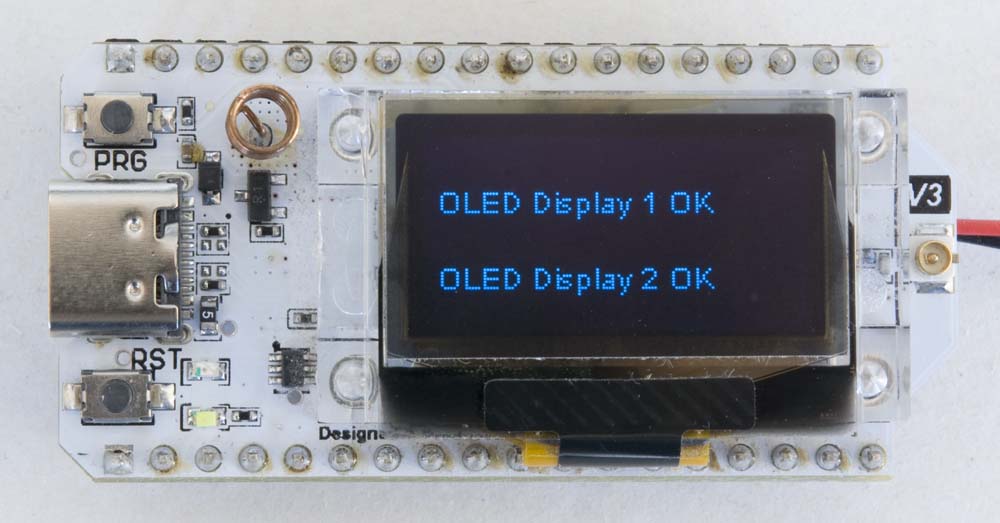
OLED display output generated by the above sketch
Unfortunately, for reasons I am yet to devine, the same is not the case for the CubeCell Dev-Board Plus (HTCC-AB02) platform. This board does use a different OLED display (SH1107 vs SSD1306) and driver (HT_SH1107Wire vs HT_SSD1306Wire)—I've not actually found any library other than the Heltec HT_SH1107Wire library that supports this display/processor combination—so this is most likely where the problem lies, rather than with anything to do with the I2C bus per sé. Either way, the equivalent (to the above) code compiles OK on a CubeCell Dev-Board Plus but, when it is loaded and executes, the display simply goes blank and the sketch hangs when attempting to execute the display() function on oledDisplay2.
Fortunately, I do not [currently] use LoRaWAN in any of my applications—I only use the LoRa layer—so the problem of using a 'second' instance on a CubeCell board has not arisen, since the only instance actually being used is the one defined in my sketches. I may have to revisit this issue if I ever get around to using LoRaWAN in my applications.
The 'Hidden' Display I2C Bus
Unlike earlier versions of the Heltec Wireless Kit 32 (HTIT-WB32), WiFi LoRa 32 (HTIT-WB32L) and Wireless Stick (HTIT-WSL) ESP32-based development boards, the OLED display on the V3 versions of these boards is configured on GPIO pins [17 & 18] that are not broken out for external use. As a result, a dedicated I2C bus must be defined to support the OLED display alone.
While these development boards do support two I2C buses, providing the capacity to support external I2C devices on a separate I2C bus, Heltec software libraries (HT_SH1107Wire and HT_SSD1306Wire) invariably use an explicit, internal instantiation of the first I2C bus to manage the on-board OLED display. This can lead to problems if there is any attempt to redefine the first I2C bus when, for example, defining the bus for use in connecting external I2C devices.
The solution to this problem then is to take care to define and use only the second I2C bus for connection to external I2C devices. The first I2C bus can still be independently instantiated in a user sketch, and used to access the onboard OLED display, it just can't be defined on GPIO pins other than those connected to the OLED display without the potential for unintended consequences.
The following example illustrates the configuration required to use the OLED display on the WiFi LoRa 32 V3 board together with an I2C BME280 atmospheric sensor.
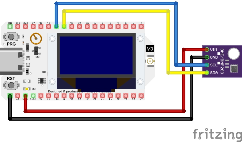
Heltec WiFi LoRa 32 V3 / BME280 Electrical Circuit
|
More generally, of course, and as discussed above, either of the two I2C buses can be defined on any two, appropriate GPIO pins. As far as the on-board display is concerned, and notwithstanding the limitations of the Heltec display support libraries discussed in the following section, pins 17 & 18 can be defined on either bus, but whichever bus that is cannot then be used to connect any other device, simply because pins 17 & 18 are not accessible.
While the V4 board also configures its display on pins 17 & 18, these are now broken out for use with other I2C devices.
Heltec OLED Display Support Software
The standard ESP8266 & ESP32 SSD1306 OLED display library (SSD1306), available through the Arduino IDE Library Manager, includes the ability to specify the bus to which the display is connected. The user has the option to specify one of the predefined instances, Wire (the default if none is specified) or Wire1, or create their own I2C bus (TwoWire()) instance, and pass a pointer to that instance when initialising the OLED display.
|
Unfortunately, for reasons best known to themselves, the Heltec developers decided against offering this option in their versions of their OLED display libraries (HT_SSD1306Wire and HT_SH1107Wire) and, as a consequence when using their libraries, the display must always be configured on the first I2C bus (Wire or some other, locally defined instance of TwoWire(0)). Where the pins for that bus have not been broken out, an instance of the second bus (Wire1 or TwoWire(1)), as illustrated in the previous example, must then be created to support any other, external I2C devices.
Note that this was never really a problem on earlier revisions of the Heltec ESP32-based boards, where the pins used to drive the on-board display are broken out for connection to other devices. When the relevant pins are accessible, there is no issue connecting other devices to the same I2C bus as the on-board display.