LoRa-Pi Board Assembly
There are currently three variants of the LoRa-Pi Hat, but they are all based on the same circuit schematic. The form factors of the three boards are slightly different, but the layout of the bottom side of the boards, the focus of most of the assembly process, is almost identical, with the only difference being the location of the LED current limiting resistors on the v1.0 board.
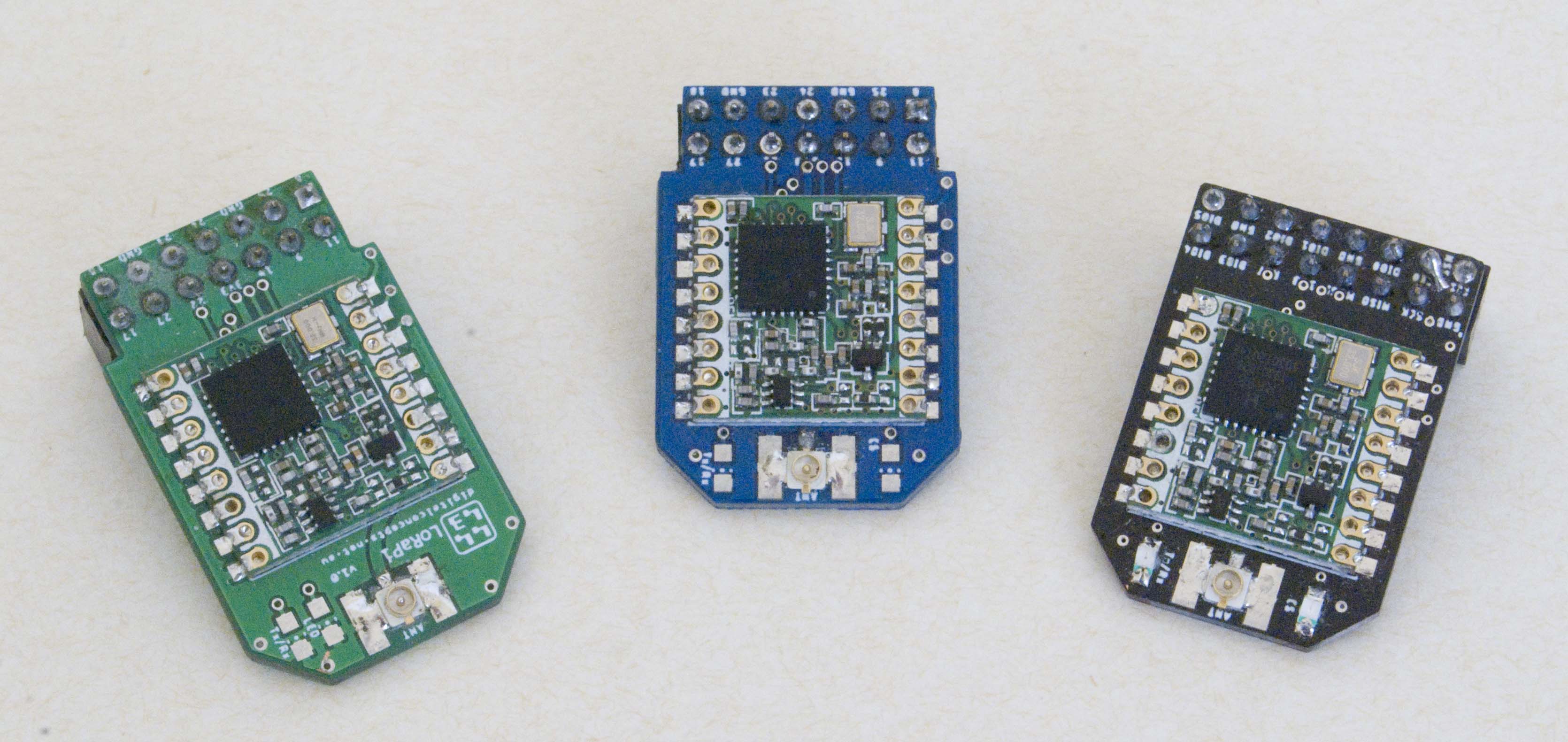
LoRa-Pi Hat Variants
The v1.0 board (at left in the above photo) is effectively obsolete—the subsequent variants are electrically identical and provide a more compact and Raspberry Pi Zero compatible package. I now actually use the v1.2 board (at centre in the above photo) for all prototyping work that does not involve a Raspberry Pi, and the v2.x boards (at right in the above photo) for all Raspberry Pi applications.
Configuration
Basic Configuration
While this board supports several configuration options, those that need to be included for basic use are:
- HopeRF RFM95W radio module
- SMA or U.FL antenna connector
- LoRa-Pi interface header
HopeRF RFM95W
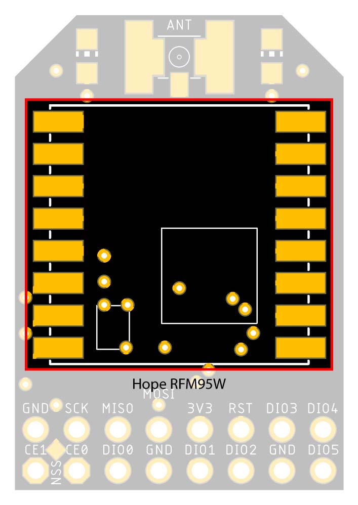
- HopeRF RFM95W radio module (U1)
HopeRF RFM95W
Antenna
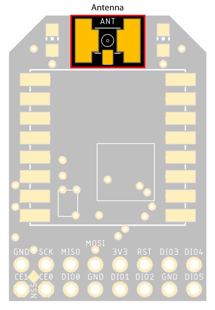
- SMA or U.FL antenna connector (A1)
Antenna Connector
All variants of the LoRa-Pi Hat support both SMA (SubMiniature version A) and Hirose U.FL or I-PEX MHF antenna connections, on a common set of pads.
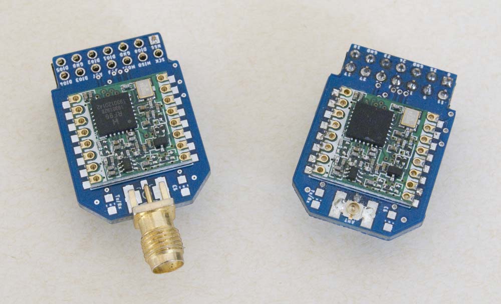
LoRa-Pi Antenna Connections
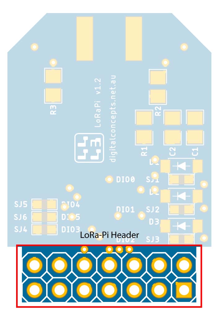
LoRa-Pi Header
| 14-Pin Header (v1.x) | 16-Pin Header (v2.x) |
 |
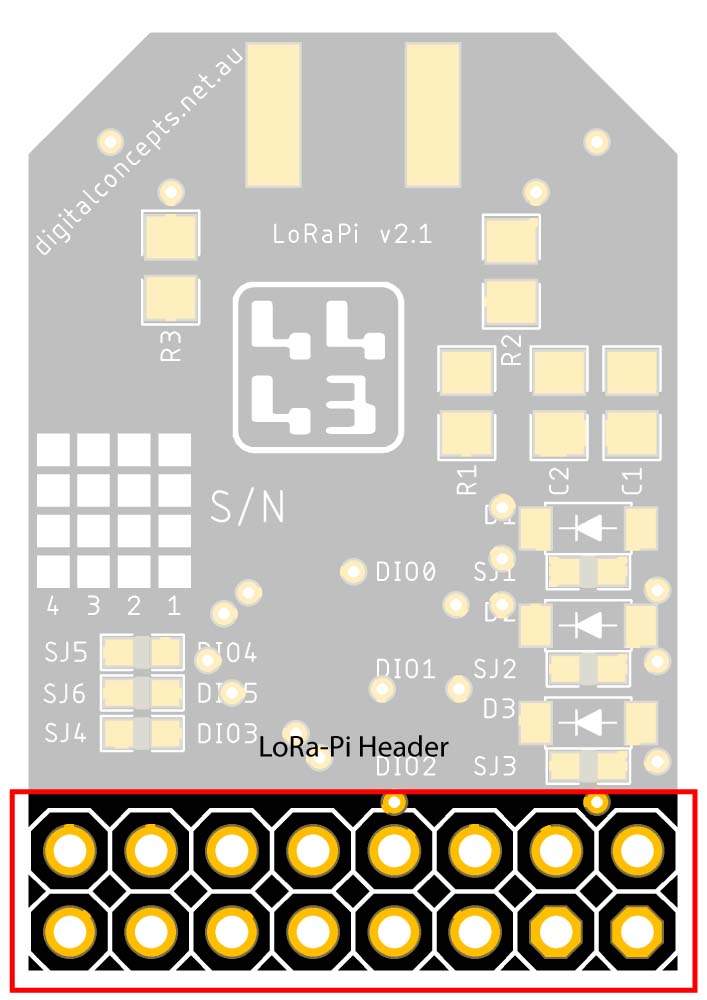 |
LoRa-Pi Header
| 14-Pin Header (v1.x) | 16-Pin Header (v2.x) |
 |
 |
LoRa-Pi Header Configuration
The basic configuration also requires the bridging of one (on the v1.x boards) or two (on the v2.x boards) solder jumpers as follows:
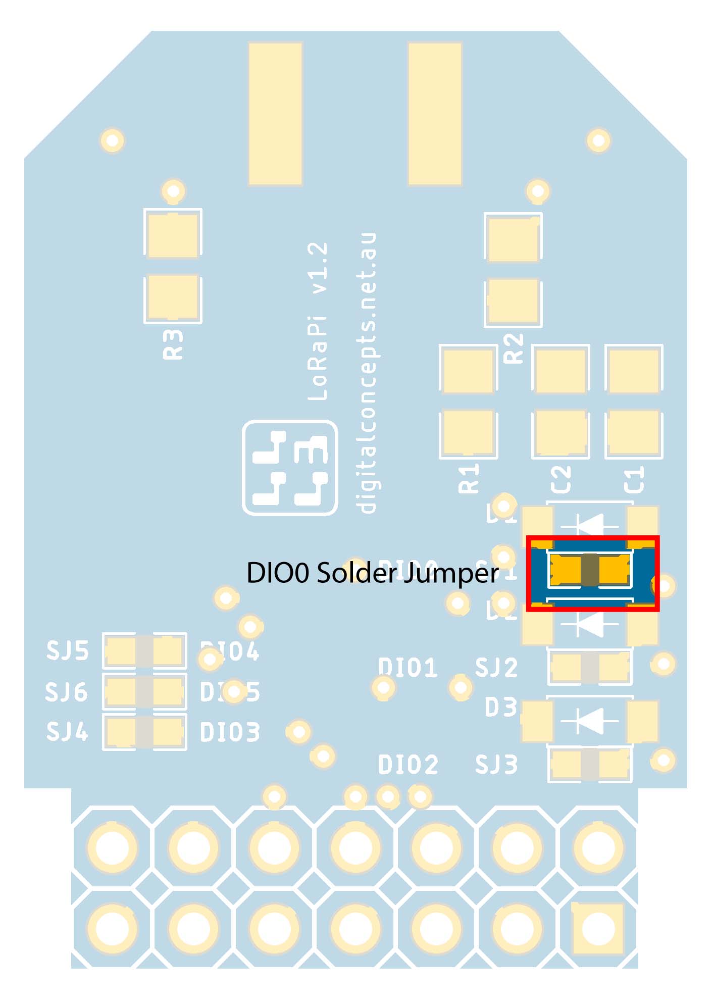
RFM95W DIO0
On all boards, a connection must be established to the RFM95W DIO0 pin. This can be achieved either by bridging the solder jumper SJ1 (as illustrated) or by configuring the diode (D1) and resistor (R1) (see LMIC Configuration below).
| DIO0 Solder Jumper Location | DIO0 Solder Bridge |
 |
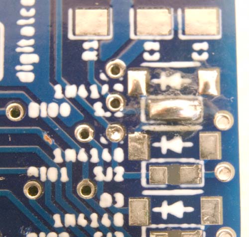 |
DIO0 Solder Jumper (v1.2 board illustrated)
RFM95W NSS
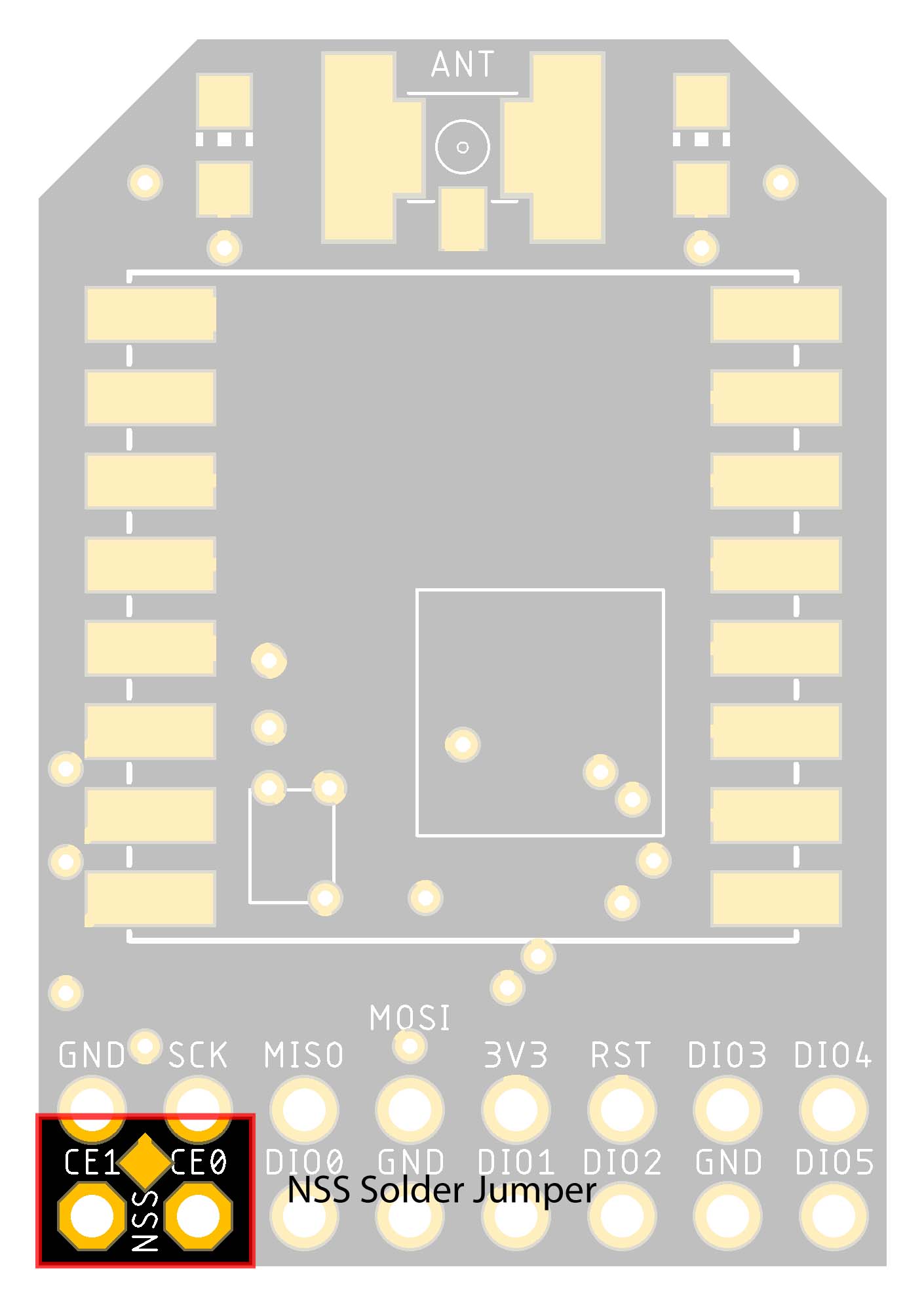
On the v2.x (16-pin) boards, a solder bridge also needs to be created between the NSS pad on the top of the board and the CE pin that is to be configured for use on the Raspberry Pi—in the present case, that's the CE0 pin, as illustrated.
| NSS Solder Jumper Location | NSS-CE0 Solder Bridge |
 |
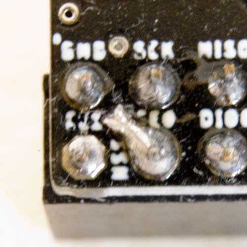 |
NSS-CE0 Solder Jumper (v2.x boards only)
This basic configuration is the only one I've actually used to date, on any of my boards. I have made up the LMIC configuration described below, to ensure that it would also work in my environment (i.e. with the DIO0 line configured through a diode, rather than just the solder bridge), but not used any of its features.
LMIC Configuration
I have assembled a complete v2.0 board in the 'LMIC' configuration but, while it is working fine in my current environment, I am yet to test the additional features when running the LMIC software.
As noted previously, this is largely a copy of the circuit designed by Charles-Henri Hallard (the link provides the development history and operational characteristics of his design), I have simply packaged the design in a more compact arrangement and provided optional connections for the RFM95W DIO pads 3–5, although I am yet to see an application that actually uses these.
Photos of assembled components (below) yet to be added...
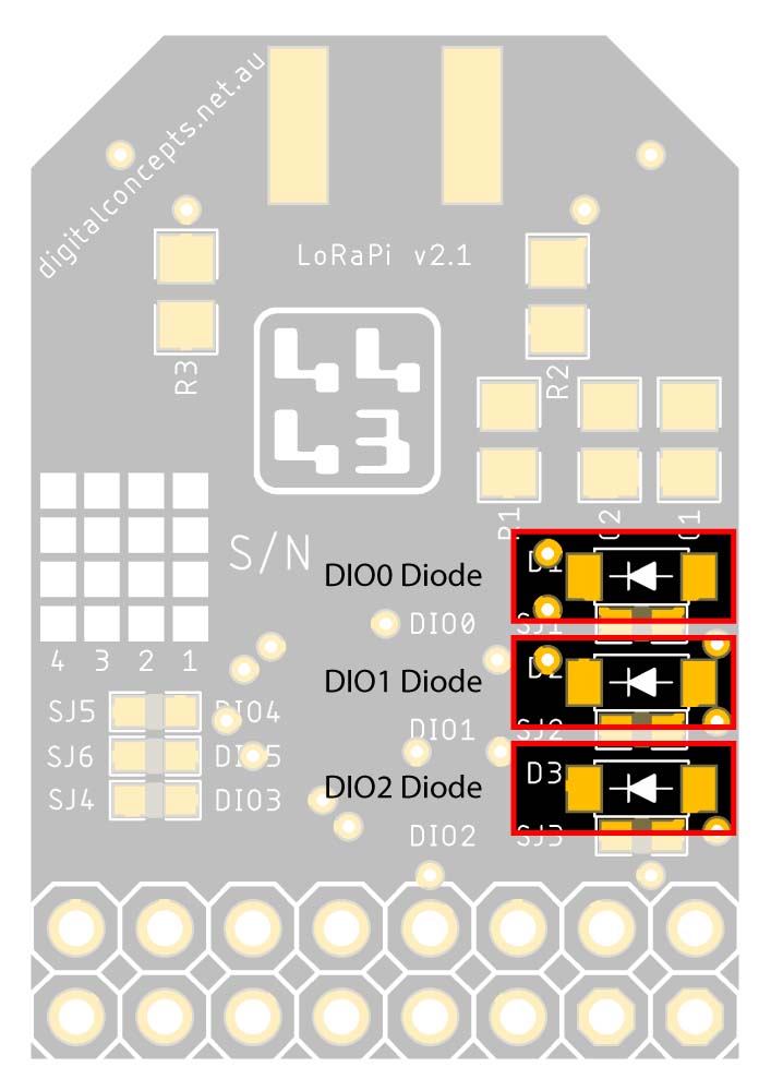
RFM95W DIO0–DIO2 Diodes
- 3×1N4148 Diode (D1–D3)
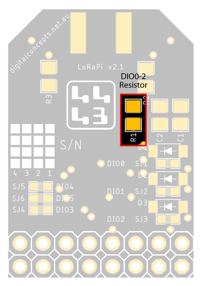
- 10k 0805 Resistor (R1)
| DIO0–DIO2 Diodes Location | DIO0–DIO2 Diodes |
 |
 |
DIO0–DIO2 Diodes
| DIO0–DIO2 Resistor Location | DIO0–DIO2 Resistor |
 |
 |
DIO0–DIO2 Resistor
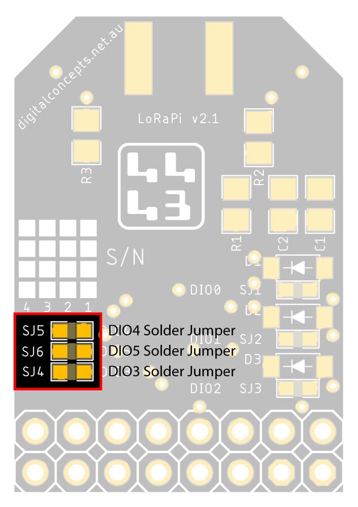
RFM95W DIO3–DIO5 Solder Bridges
| SJ4–SJ6 Location | SJ4–SJ6 Solder Bridges |
 |
 |
Solder Jumpers (SJ4–SJ6)
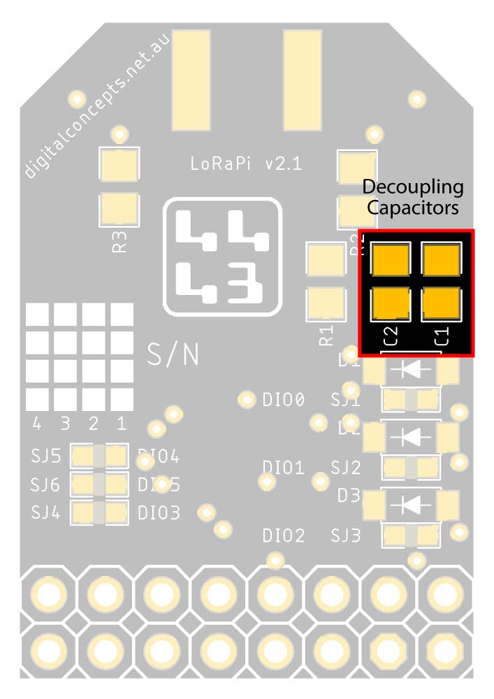
Decoupling Capacitors
- 1µF 0805 Capacitor (C1)
- 10µF 0805 Capacitor (C2)
| Decoupling Capacitor Location | Decoupling Capacitors |
 |
 |
Decoupling Capacitors
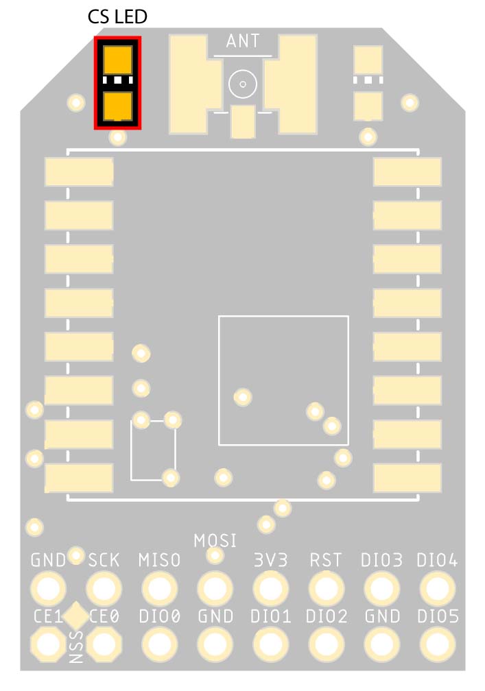
Status LED
- 0805 LED (L1)
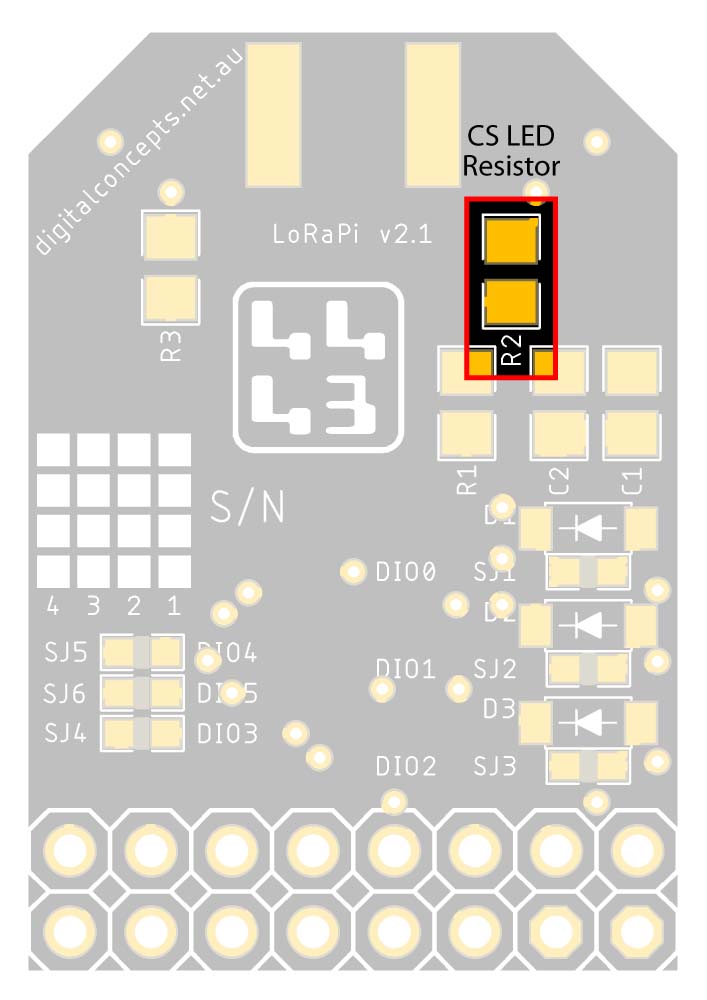
- 390Ω 0805 Resistor (R2)
| Status LED Location | Status LED |
 |
 |
Status LED
| Status LED Resistor Location | Status LED Resistor |
 |
 |
Status LED Resistor
The Status LED lights when the radio is ready to transmit or receive data.
Activity LED
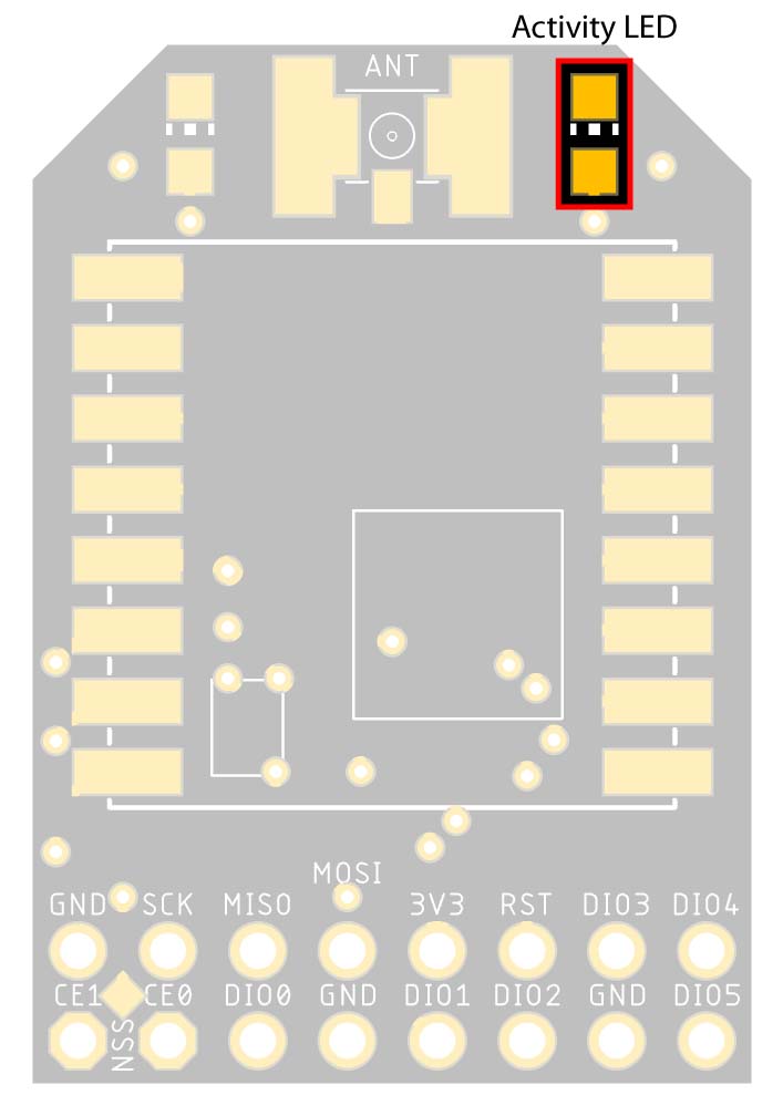
- 0805 LED (L2)
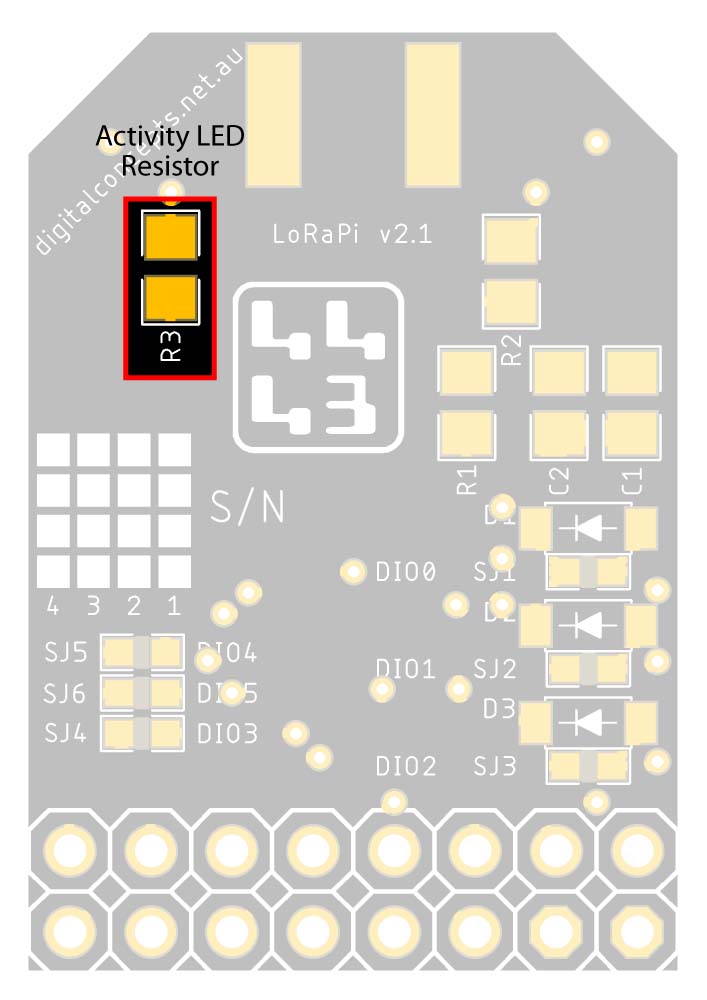
- 390Ω 0805 Resistor (R3)
| Activity LED Location | Activity LED |
 |
 |
Activity LED
| Activity LED Resistor Location | Activity LED Resistor |
 |
 |
Activity LED Resistor
The Activity LED lights when the radio is transmitting or receiving data.

