Reliable Packet Delivery Protocol (RPDP)
In order to support an application that involved the control of a pump, or more generally any powered device, it was necessary to have some way to be sure of the state of the pump, or powered device. I had been using a commercial system that employed a proprietary communications protocol, but this system had failed on two occasions with the result that the pump under control did not turn off when it was supposed to, with the result that the entire contents of a water tank were lost.
Requirement
I have seen a form of reliable packet delivery in some [LoRa] radio libraries. To date, however, the only one I have found uses what is essentially a 'blocking' mechanism whereby the sending node waits for confirmation of receipt before proceeding or performing any other functions. This may be less of an issue for an End Node, which may be doing little more than sending periodic updates to a Gateway Node. The Gateway Node, however, will generally be managing communications with several End Nodes and can't really afford to be sitting around idle, just waiting for an individual End Node to acknowledge a transmission.
Nonetheless, in the present case, the protocol required to support the reliable delivery of packets does not need to be as complex as something like the Transmission Control Protocol (TCP) used in the Internet. There is no need to set up and maintain sessions as such, we just need to know whether or not individual instruction packets are being received and that the status of the remote device, at any point in time, is being accurately represented on our Node‑RED dashboard. In our LoRa environment there is also no routing per sé, as we are only dealing with simple wireless broadcast communications.
As such, all we need is something like a simple version of the ALOHA protocol, which was actually designed for a radio communications network.
Our fundamental requirement would be satisfied by a simple protocol that involved the formal acknowledgement of the receipt of a data packet transmitted over our LoRa network—MQTT runs on a TCP session, so this element of the communication sequence is inherently reliable. It will still be up to the Nodes involved, invariably a Gateway and an End Node, to act on the receipt of this formal acknowledgement, or failure thereof. Ultimately, the End Node would have some default fall-back state if no communications had been received for some predefined period of time, avoiding the problem of unknowingly emptying a tank, if the End Node were controlling a water pump for example, when this was not the intention.

Reliable Packet Delivery Messsage Sequence
While, in our most basic application, there might only be a single data stream between a gateway and a single end point, controlling a single device, that might not be the more general case where, for example, a Gateway Node may be involved in the control of several pumps, or other powered devices, perhaps managed by several independent Controller Nodes. As a result, we also needed to be able to manage the situation where more than one packet might be awaiting acknowledgement at any point in time.
Update: 4 Oct 2023 While not directly related to the RPDP as such, the [Heltec WiFi LoRa 32] ESP32 node that I use as the Gateway Node loses its WiFi connection a little more often than I would like, with the result that the MQTT session is also lost. The RPDP does guarantee the delivery of any instruction that might arise from the receipt of an MQTT message by a Gateway from an upstream broker, but it cannot do the same in relation to delivering MQTT messages to a broker. It is, therefore, important that applications appropriately manage the potential failure of upstream services such as the loss of communication with an MQTT broker.
Implementation
In the event, the primary objectives of the protocol were simply to:
- Allow the sending Node to identify whether or not a packet required acknowledgement
- Support acknowledgement of the receipt of any such packet
- Support multiple, concurrent reliable data exchanges between a Gateway Node and any number of End Nodes
While not really part of the protocol per sé, there was also the need to support MQTT monitoring of the status of an acknowledged, or so-called reliable data exchange.
Noting that neither the Type nor Length fields in the existing packet structure were fully utilised, it was a simple matter to modify this structure to support the needs of our reliable delivery protocol. In addressing the first objective above, the top bit of the original Type field was assigned for use as the REL (RELiable) bit, signalling that the packet in question required acknowledgement. The top bit in the original Length field was then assigned for use as the ACK bit, to indicate that a packet was simply an acknowledgement of receipt of a particular packet that required reliable delivery.
There was an element of logic involved in this final arrangement. If a packet of any particular Type required reliable, or acknowledged, delivery, the top bit of the original Type field would be set to 1, otherwise it would be as it was previously, set to 0. To acknowledge receipt of a packet, it was noted that only the information in the header of a packet was required to uniquely identify that packet, so there was no need to include any payload, the Length field would be 0, and using any part of that field to specifically identify it simply as an acknowledgement of receipt of the packet identified by the header data would be fine.
The resulting, amended packet structure is now as illustrated below.

Packet Structure (Reliable Delivery)

|
Langlo Packet Structure (Reliable Delivery).docx | [82 KB] |
The third objective was addressed by creating a buffer to store copies of packets awaiting confirmation of delivery. The buffer is implemented as a linked list managed through Ivan Seidel's LinkedList library. In our environment then, an element in the buffer list, and the buffer list itself, are defined as follows:
Packet Buffer Construct#include <PacketHandler.h>// LoRa Packet management #include <LinkedList.h>// Linked List support for ACK buffer struct bufferElement { PacketHandler packet; unsigned long startTime; int resendCount; }; LinkedList<bufferElement> *ackBuffer = new LinkedList<bufferElement>(); |
Each entry in the buffer list comprises a copy of the packet that is to be acknowledged, the time at which the packet was placed in the buffer list and a count of the number of attempts that have been made to deliver the packet.
Four new [PacketHandler] methods have been introduced to support the setting and retrieval of the REL and ACK bits:
|
void setRelFlag(); bool relFlag(); void setAckFlag(); bool ackFlag(); |
In the present implementation, setting the packet Type (packet.setPacketType(packetType)) for a packet (packet), as one would normally do before populating a packet with data, automatically sets the payload byte count (Length) for that packet type and zeros both the REL and ACK bits. Further, setting the ACK bit (packet.setAckFlag()) for a packet automatically sets the payload byte count (Length) to zero, since there is no payload in an acknowledgement packet. Setting the REL bit (packet.setRelFlag()) simply sets the REL bit to one.
When constructing a packet, then, one should always set the packet Type first, then set the REL and/or ACK bits as required.
Operation
The following are the declarations supporting the reliable delivery protocol described and illustrated below. Note the distinct declarations required for the different timer functions used for ESP32 and ASR650x processors—more detail is provided by following these respective links to the pages describing the specific characteristics of the two processors.
Declarations#include <LoRaWan_APP.h>// LoRa #include <WiFi.h>// WiFi client #include <PubSubClient.h>// MQTT client #include <PacketHandler.h> // LoRa Packet management #include <LinkedList.h>// Linked List support for ACK buffer #include <Ticker.h>// Asynchronous timer (ESP32 only) PubSubClient mqttClient(localClient), *mqttClientPtr; bool newMessage = true; bool ackRequired = true; uint32_t messageCounter = 0; uint32_t pumpMAC = 0; uint8_t pumpId = 0; PH_powerStatus pumpPowerState = PH_POWER_OFF; PH_packetType ackPacketType, messageType; PacketHandler inPacket; const int resendInterval = 1; // Seconds const int millisResendInterval = resendInterval * 1000; const int resendLimit = 3; int bufferSize = 0; int resendCount = 0; bool ackReceived = false; bool checkBuffer = false; bool resendTimerActive = false; struct bufferElement { PacketHandler packet; unsigned long startTime; int resendCount; }; bufferElement element; LinkedList<bufferElement> *ackBuffer = new LinkedList<bufferElement>(); // Timer for ESP32 processors Ticker resendTimer; // Timer for ASR650x processors static TimerEvent_t resendTimer; |
The MQTT client library (<PubSubClient.h>) is, of course, only required in Gateway Nodes.
Sending Packets
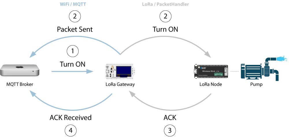
Logically enough, a reliable packet exchange must be initiated by the sending Node. In its most basic form, a reliable packet exchange will proceed as follows:
- The sending Node will construct the relevant packet then invoke the
setRelFlag() function to set the REL bit, indicating that the recipient should acknowledge receipt of this packet; - The sending Node records the current time, zeroes the resendCount and places the element containing the packet in its acknowledgement buffer list;
- The sending Node invokes the resend timer;
- The sending Node transmits the packet and, under normal circumstances, the receiving Node will, at the same time, receive the packet;
- The receiving Node must check all incoming packets to determine whether or not the REL bit is set and having noted that the REL bit is set on this packet, constructs a corresponding acknowledgement packet;
- The original receiving Node transmits the acknowledgement packet and, under normal circumstances, the original sending Node will, at the same time, receive it;
- The original sending Node must check all incoming packets to determine whether or not the ACK bit is set and having noted that the ACK bit is set on this packet, searches its acknowledgement buffer list for a matching packet;
- On finding a match, the original sending Node deletes the original copy of the packet from its acknowledgement buffer list.
Both the receiving and sending Nodes will usually perform some action in response to either the receipt of a packet or acknowledgement of its receipt respectively.
In my pump controller application, for example, an MQTT message, instructing a Pump Controller Node to turn a pump ON or OFF, will trigger the sending of a PUMP Type packet from the Gateway to the Pump Controller Node (see MQTT Queuing for details on the handling of MQTT Call-Back messages). In order to ensure that the instruction is received by the Pump Controller Node, or to determine that there has been a communications failure, the Gateway Node will set the REL bit in this packet. On receiving the control instruction, the Pump Controller Node will turn the pump ON or OFF, as instructed, and send an acknowledgement packet (in practice this simply involves reversing the source and destination MAC addresses and setting the ACK bit in the received packet) back to the Gateway Node. The Gateway Node will then advise the MQTT broker that the original command has been acknowledged. In my application, the Gateway Node also sends an MQTT message to advise the broker when it sends the instruction to the Pump Controller Node. In this way, a communications failure might more easily be attributed to either the Gateway or Pump Controller Node.
Resending Packets
But what if, for one reason or another, the intended receiving Node does not receive the original packet? As noted in Step 3 above, when sending a packet that requires acknowledgement, the sending Node invokes a resend timer. If no acknowledgement has been received when the resend timer expires, the following occur:
- When the sending Node's resend timer expires, a flag is set to trigger examination of its acknowledgement buffer list;
- If the buffer list is not empty, and starting at the head of the list, the sending Node checks the
startTime, the time the packet was sent, recorded for the next list element; - If more than a predefined time has elapsed since the element's
packetwas sent, the sending Node next checks the element'sresendCount; - If the resend count has not been exceeded, the packet is resent, the
startTimeis reset, theresendCountincremented, the element is moved to the end of the buffer list and the processing cycle skips to Step 7; - If the predefined time for the element being examined has not expired, the process cycles back to Step 2, moving to the next element in the buffer list. This cycle continues until a packet is resent or the last element in the list has been examined;
- If the
resendCountfor an element has been exceeded, that element is simply deleted from the buffer list and the process cycles back to Step 2. If the sending Node needs to raise some alarm to signal that a packet has not been acknowledged, that is done at this point; - If the buffer list is not empty, the sending Node restarts its resend timer;
- The sending Node cycles back into RX_State;
- The sending Node processes received packets as specified in Steps 7 and 8 of the original sending sequence above.
The resend process only deals with a single packet retransmission in any one cycle. Each cycle takes ~100-150ms, which is also close to the time it takes for the receiving Node to acknowledge receipt of a packet. If the sending Node had continued processing packets from the acknowledgement buffer, if indeed there were more to process, there is a high probability that it would not be in receive mode when the acknowledgement of the previous packet was sent. With only a single retransmission being processed in a cycle, moving the relevant element to the end of the buffer when it has been processed then provides an element of 'fairness' in processing any other queued elements in subsequent cycles.
Example Code Elements (MQTT for ESP32 processors only)void setup() { // Timer setup for ASR650x processors TimerInit( &resendTimer, resendFunction ); TimerSetValue( &resendTimer, millisResendInterval ); } void loop() { . . switch ( state ) { case TX_State: { . . if ( sendAck ) { // Acknowledge any packets that require an ACK . . } if ( checkMqttBuffer ) { // Send any packets in the MQTT buffer . . } if ( checkAckBuffer ) { // If there is one, check the first element of the ACK buffer // We only do one resend per cycle so as not to block a response to the packet // that is sent bufferSize = ackBuffer->size(); while ( bufferSize > 0 ) { unsigned long currentTime = millis(); unsigned long timeInterval; element = ackBuffer->get(0); timeInterval = currentTime - element.startTime; if ( timeInterval > millisResendInterval ) { resendCount = ++element.resendCount; if ( resendCount > resendLimit ) { element = ackBuffer->remove(0); // Want to send something to the MQTT broker at this point... switch ( messageType ) { case PUMP: { // A "State Undefined" message element.packet.setPumpState(PH_POWER_UNDEFINED); element.packet.mqttOut(mqttClientPtr); break; } // Other specific cases as required... } bufferSize = ackBuffer->size(); } else { // Move the element to the end of the queue element = ackBuffer->remove(0); element.startTime = currentTime; element.resendCount = resendCount; ackBuffer->add(element); // Resend the packet sendMessage(element.packet); delay(100); // We need to go see if there's a response to this transmission, so we'll // pretend the buffer's empty to get us out of the buffer processing loop bufferSize = 0; } } } // We will have exited the loop after resending just one packet, so we need to // check to see if there's still more in the buffer that we need to come back for bufferSize = ackBuffer->size(); if ( bufferSize > 0 ) { if ( !resendTimerActive ) { // Timer for ESP32 processors resendTimer.once( resendInterval, resendFunction ); // Timer for ASR650x processors TimerStart( &resendTimer ); resendTimerActive = true; } } } messageCounter++; state = RX_State; break; } case RX_State: { if ( lora_idle ) { lora_idle = false; Radio.Rx(0); } Radio.IrqProcess(); break; } default: { state = RX_State; break; } } } void OnRxDone( uint8_t *payload, uint16_t size, int16_t rssi, int8_t snr ) { inPacket.begin(); inPacket.setContent(payload,size); Radio.Sleep( ); if (inPacket.destinationMAC() == myMAC) { uint8_t byteCount = inPacket.packetByteCount(); if (inPacket.verifyPayloadChecksum()) { if ( inPacket.ackFlag() ) { if ( verifyAck(inPacket) ) { // Use the original packet, which includes the payload, as the basis for the MQTT message // Need to switch the Destination and Source MAC addresses to match the ACK packet though... element.packet.setDestinationMAC(inPacket.destinationMAC()); element.packet.setSourceMAC(inPacket.sourceMAC()); element.packet.mqttOut(mqttClientPtr); } } else { inPacket.mqttOut(mqttClientPtr); } } else { // Invalid checksum, discard packet inPacket.erasePacketHeader(); } } else { // No need to go any further inPacket.erasePacketHeader(); } lora_idle = true; } void resendFunction() { int bufferSize = ackBuffer->size(); if ( bufferSize > 0 ) { checkBuffer = true; state = TX_State; } else { checkBuffer = false; } resendTimerActive = false; } bool verifyAck( PacketHandler ackPacket ) { // Search the buffer for a matching outstanding ACK int i = 0; int bufferSize = ackBuffer->size(); bool found = false; while ( i < bufferSize && !found ) { element = ackBuffer->get(i); ackPacketType = ackPacket.packetType(); if ( ackPacket.sourceMAC() == element.packet.destinationMAC() && ackPacket.sequenceNumber() == element.packet.sequenceNumber() && ackPacketType == element.packet.packetType() ) { element = ackBuffer->remove(i); found = true; } i++; } return found; } |
Reciprocal Arrangements
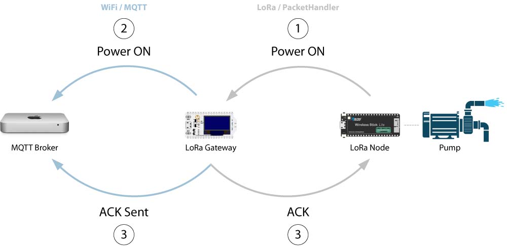
My pump Controller Node also includes a manual override capability, so that the attached pump can be turned ON or OFF locally. The need for this action, initiated by the Controller Node, to also be reliably represented on our Node-RED dashboard, effectively requires the implementation of reliable delivery in the reverse direction. Accordingly, the same capabilities, to both initiate and respond to requests for packet acknowledgement, can be implemented on either the Gateway Node or any Node in the network that is required to support a local control function.

Local Override Messsage Sequence
Hardware Considerations
To date, I have implemented RPDP on both ESP32 (Heltec WiFi LoRa 32 V3 and Heltec Wireless Stick Lite V3, although this code should run on any ESP32 platform using appropriate LoRa access methods) and ASR650x (Heltec CubeCell) platforms. Communication with an MQTT broker, however, requires [IP] network access, and this is only possible on the ESP32 configurations, with their WiFi connectivity. Accordingly, in the present context, Gateway functionality is only available on ESP32 platforms.
The implementation of the timer function used in the packet resend process is also platform specific—the ESP32 uses the Ticker library (the Bert Melis version—the Stefan Staub version uses a slightly different call structure but could easily be adapted to the present environment), while the CubeCell uses a timer managed through its onboard Real Time Clock (RTC).
Example Sketches
The following are the sketches used in the RPDP test environment (see here for a description of the final implementation), which comprised a Heltec WiFi LoRa 32 V3 Dev-Board operating as the gateway, with pump controller test software configured on CubeCell (the processor currently used in the Pump Controller Node that is under development), CubeCell Plus and Wireless Stick Lite V3 Dev-Boards. The test environment 'pump controllers' were initially configured with an interrupt on the respective board's USER button to simulate the local override function. The CubeCell and CubeCell Plus seemed to trigger frequent interrupts spontaneously in this configuration, so the CubeCell interrupt is configured on GPIO3 and the CubeCell Plus on GPIO11, the latter to be consistent with the interrupt button configured on v2.3 and later of the 100689-BHCP PCB used in other CubeCell Plus Node configurations.
These sketches are still evolving as I encounter behaviours that were either unintended, ultimately considered undesirable or indeed presented improvements on the original implementations.

|
WiFi LoRa 32 V3 Gateway 0.0.14 | 09-Jul-2023 | [13 KB] |

|
WSL V3 Pump Controller 0.0.14 | 09-Jul-2023 | [8 KB] |

|
CubeCell Pump Controller 0.0.14 | 09-Jul-2023 | [8 KB] |

|
CubeCell Plus Pump Controller 0.0.14 | 09-Jul-2023 | [9 KB] |
The above sketches were developed using the PacketHandler 0.0.14 library package (but any correlation between the version numbers of the individual sketches and that of the PacketHandler library is purely coincidental).
This test environment is managed through Node-RED and a Mosquitto MQTT broker.
There's very little to do in setting up Mosquitto. I have used this broker on both macOS and Raspberry Pi hosts and in both cases this involves little more than installing and starting the application.
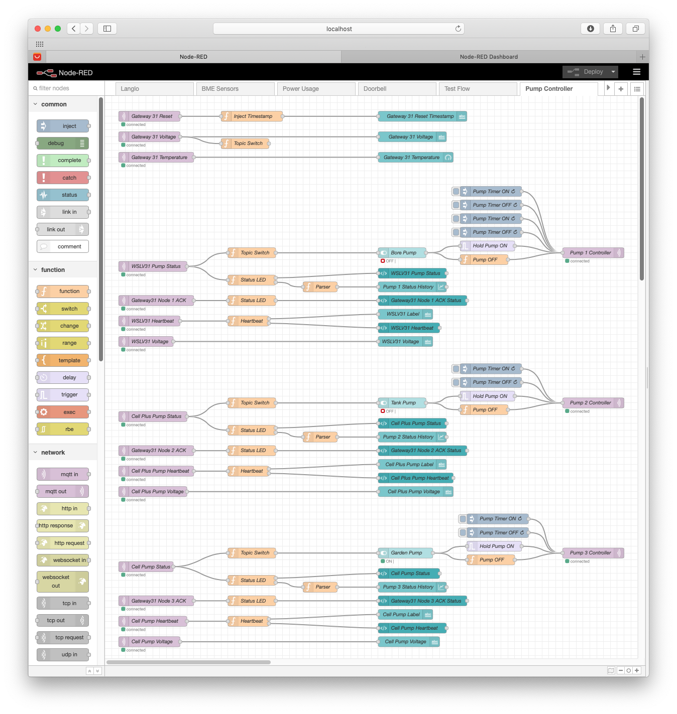
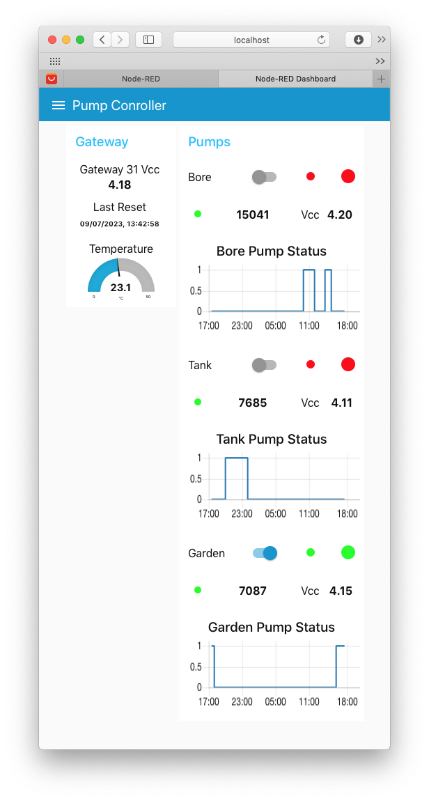
The Node-RED flow used with this test set-up is illustrated below.
| Flow | Dashboard |
|---|---|
 |
 |
Node-RED Flow and Dashboard

|
Node-RED Flow | 11-Jul-2023 | [10 KB] |
By way of brief explanation of the appearance of the above Pump Controller Node-RED Dashboard displays, each effectively comprises three rows. The first includes an identifying label, a switch indicator representing the MQTT broker's view of the pump state (OFF or ON), and two status 'LEDs', the smaller one indicating the Gateway's view of the pump state (red = OFF, green = ON, orange = Unknown, indicating that the Controller Node has not responded to the last control message) and the larger indicating the Controller's view of the pump state (red = OFF, green = ON)—when errors occur, these help to identify the source. The second line includes the heartbeat 'LED' (green when the Controller is 'alive' or red when no message has been received from the Controller for 5 minutes or more) and the Controller's message counter and battery voltage. A 24hr graph of the pump state (0 = OFF, 1 = ON) history is presented in the third row.

