Microchip Technology ATmega328[P]
Pin Definitions
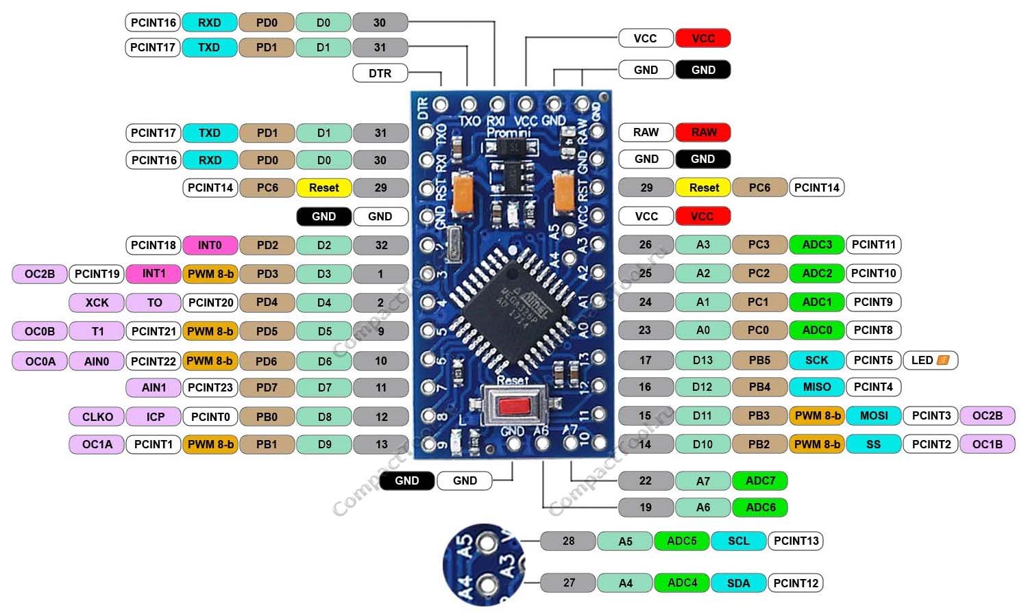
The Arduino Pro Mini is an open hardware platform developed by SparkFun Electronics. There are numerous implementations of this platform and while the logical pin configurations are generally consistent, the physical layout of pins can vary slightly between implementations. The variant that I have used for all of my applications is illustrated in the following pinout diagram.

Note that analog pins on the Pro Mini board, which can be used for either analog or digital I/O, are numbered with an "A" prefix. Digital pins are simply numbered numerically, according to their GPIO number. The two exceptions are the RXI ([digital] pin 0) and TXO ([digital] pin 1) pins.
1 2 3 4 5 6 7 8 9 10 11 12 13 14 15 16 17 18 19 20 21 22 23 24 25 26 27 28 29 30 31 32 33 34 35 36 37 38 39 40 41 42 43 44 45 46 47 48 49 50 51 52 53 54 55 56 57 58 59 60 61 62 63 64 65 66 67 68 69 70 71 |
// Predefined pin identifiers
/* A0 A1 A2 A3 A4 A5 A6 A7 */ #define Builtin_LED13 #define D00 #define RX0 #define RXI0 #define RXD0 #define D11 #define TX1 #define TXO1 #define TXD1 #define D22 #define INT02 #define D33// PWM #define INT13 #define D44 #define T04 #define D55// PWM #define T15 #define D66// PWM #define AIN06 #define D77 #define AIN17 #define D88 #define D99// PWM #define D1010// PWM #define D1111// PWM #define D1212 #define D1313 #define ADC0A0 #define ADC1A1 #define ADC2A2 #define ADC3A3 #define ADC4A4 #define ADC5A5 #define ADC6A6 #define ADC7A7 // SPI (RFM95W) #define SCK13 #define MISO12 #define MOSI11 #define NSS10 #define RST-1 #define DIO05 // I2C #define SDAA4 #define SCLA5 // ALF4all #define A4a_A0A0 #define A4a_A1A1 #define A4a_A2A2 #define A4a_A3A3 // Sensor Interface #define sensorWakeA0 #define sensorInterruptA1 |
LoRa MAC Address
To derive a four byte MAC address for the ATmega processors that are used in the present network, a local prefix of 0xDC has been prepended to the last three bytes of the processor serial number that can be retrieved using the ArduinoUniqueID library and example sketch—in the present case, for all of the ATmega processors used, the first six bytes of the [nine byte] ID are identical in any case.
| Arduino Unique ID | 0x |
| Langlo MAC Address | 0xDC |
There is, of course, no guarantee that this derived MAC address or even the precessor ID will be globally unique (i.e. form the basis of a valid TTN EUI), but it serves its purpose in the present environment.
Memory Usage
I bumped into memory problems with the Pro Mini very early on, when I tried to configure an OLED display in addition to the RFM95W radio. In that case, the relevant sketch would compile, but would never actually run. I noted the compilation comment that memory usage was high, but I had no idea what the implications were at the time.
When I finally got around to migrating the packet management software to a common library, the sketch for a simple BME280 sensor configuration wouldn't even compile, reporting that Global variables were consuming 175% of the 2Kbyte SRAM provided for this purpose (but also for the storage of local variables) on the Pro Mini.
This Atmel Application Note provides a good overview of how to optimise memory usage on the 8-bit Atmel MCUs. Ensuring that variables are only made global when absolutely necessary is the first consideration mentioned, but this had very little impact in the present case—just a few bytes here and there. It eventuated that what was consuming a significant amount of memory, hundreds of bytes, were literal strings in print statements, all of which are stored in SRAM by default. The F() macro can be used to move these entities onto the stack in program memory and free up space in SRAM.
The other significant user of SRAM was the nodeID list included in the NodeHandler library, which is used by the Packet Handler and includes two literal strings (10-20 bytes each) for each Node listed. This list is used mainly by a gateway Node, as it records the relevant characteristics of individual Nodes in the network. This was only ever intended to be an interim solution—the intention was always to ultimately make Node recognition by the gateway dynamic, so that only the details of active Nodes would ever need to be retained, and even this information would be stored in program memory.
To avoid that last problem, the NodeHandler nodeID list is not accessible on the Pro Mini platform. Individual Pro Mini Nodes must provide the relevant details to their local instance of the Packet Handler. For the time being, this requires the user to coordinate the details of individual Pro Mini Nodes, within their respective sketches, with the content of the NodeHandler nodeID list (in the NodeHandler library).
Analog-to-Digital Converter (ADC) Usage
The Pro Mini Atmega328P ADC has a maximum input voltage of 3.3V and 10 bit [0..1023] resolution.
Further details pending
EEPROM Usage
Refer to the discussion on EEPROM usage in the description of the EepromHandler library.
Note that when using the ResetEEPROM utility discussed therein, the Arduino Pro Mini does not seem to be able to handle IDE Serial Monitor input at 115200bps. To get this sketch to operate as intended, I've had to lower the baud rate—I've not worked out the exact maximum that can be handled, but the sketch does accept Serial Monitor input correctly using a baud rate of 9600bps.
Note also that the I2C bus should not be clocked over 100KHz when using the Pro Mini to access a Microchip AT24Cxx EEPROM.
Processor Interrupts
Details pending

