Project Background
This page started out as a bit of a quick and dirty exercise to make the below-listed files available. It contains some project background information, my original breadboard 'experiments' with Node configurations, and the basic code examples that were the foundation of much of what I've done since then. Things have progressed a bit in the intervening years, but I am yet to get back to this section to properly tidy it up.
Please note that the files provided herein are merely a snapshot of the 'proof of concept' set-up that underpinned this project. I have endeavoured to update relevant sketches at logical points in the development cycle, but I make no claim in relation to the integrity of anything herein, nor do I offer any commitment to ensure that anything provided in the future will be compatible with anything that has been provided at an earlier date. I will, however, do my best to ensure that everything, at any point in time, is internally compatible—if you download the whole lot at once (click here to download the last [11 Apr 2020] full code package associated with this initial work), everything should interoperate as intended.
Having said that, more recent, and probably more relevant software 'releases' can be downloaded from the Software pages, as noted below (see Update: 23 Mar 2023).
Update: 8 Aug 2021 Having recently acquired a Nordic Semiconductor PPK2 power profiler, I have started to work a little more conscientiously on minimising power usage. I have created an Arduino Pro Mini sketch, based on that of Wijnand Nijs, to use the BCS-A4a sensor/power board TPL5111/TPS22860 timer/switch combination to shut down the processor when not in use (1.5µA), and I have updated the CubeCell scripts to properly enter deep sleep (2.5µA)—see below.
Update: 23 Mar 2023 I have recently developed several software libraries in which to maintain common source code for my sketches. The downloads available through this page predate this work. I've left them here because they might be of assistance to someone wanting to work through exactly what is going on—all the necessary code is included in these sketches, with the only library dependencies being those available through the Arduino IDE.
Code examples provided elsewhere on this site, however, are based on my PacketHandler/NodeHandler/EepromHandler libraries. The EepromHandler introduced an extended EEPROM 'data map', so that code that uses the EepromHandler will not be compatible with 'manual' EEPROM access methods that predate this. The packet structure, however, hasn't changed so, at that level, PacketHandler code should be compatible with the sketches provided below.
Either way, I would recommend using the sketches available under the Software pages where ever possible. They are generally 'tidier' and reflect the development that has been undertaken in the interim.
Unfortunately, I've not been able to create a 'full code package' since that original 11 Apr 2020 version referenced above, but current versions of the essential support files are available through the Packet Handler > Downloads page.
Please note also that, if you are using one of the Heltec CubeCell development boards, you will need to use the individual versions of sketches provided below, or those available through the Packet Handler > Downloads page, once again not the ones provided in the 'full code package' described above, to be compatible with the current Heltec [Arduino IDE] software environment.
Motivation
The main reason for providing the sketches and scripts herein is that I would have appreciated a starting point when I began working to get the different modules and configurations communicating with each other. To that end, these sketches and scripts provide that starting point for anyone else who might be interested.
This project grew out of a personal education exercise that itself followed my discovery of Arduino processors. I acquired a number of different MCUs, initially for no other real purpose than to explore how they worked. That grew into the exercise of getting the different processors to communicate with each other and that in turn gave rise to the 'bigger picture' umbrella under which I am now working (or maybe that should really be 'playing'). I didn't really set out to create an integrated water management system, that just became the justification for spending the time and money on all of the associated 'toys'.
Nonetheless, all of the hardware configurations described herein 'work' (many have been running now for several years), and all of the modules communicate [still LoRa only at this stage] with the gateways as intended.
Operating Environment
The configuration described in the files below comprises a series of LoRa nodes, implemented on a range of processor modules, that communicate with a LoRa gateway that subsequently processes received data and creates MQTT messages that are forwarded to a host running Node-Red and Mosquitto. The ultimate goal is to move both of these latter functions, the LoRa[/LoRaWAN] gateway and the Node-Red/Mosquitto server, to a Raspberry Pi platform, and integrate all that with InfluxDB and Grafana.
The set-up is basically as illustrated (click on the image to enlarge).

Individual nodes are configured to transmit a variety of data at one minute intervals (in practice, with various other delays in the current code, this ends up resulting in around 50 transmissions per hour). Some nodes are configured with actual [BME] sensors while others simply transmit preset values for the purpose of establishing a test environment with a number of nodes transmitting different information to the gateway. The transmission frequency is much higher than will ultimately be required but was chosen to both load the network to the point where transmission collisions occurred frequently enough to test the resilience of the software and to test battery life under extreme conditions.
Hardware
There are currently code modules for each different processor that I've worked with to date. Some elements are still specific to the individual modules, but I would expect to ultimately get to a point where any differences can be accommodated in module-specific libraries and the core code would be common to all. Nonetheless, the modules I've used, and individually coded, are:
- Heltec WiFi LoRa 32
- Heltec Wireless Stick Lite
- Heltec CubeCell and CubeCell Plus
- Elecrow ESP32S WiFi/BLE Board (with RFM95W)
- Amica NodeMCU DevKit (with RFM95W)
- Arduino Pro Mini (with RFM95W)
- Raspberry Pi Zero W (with RFM95W)
More recently, I have also developed boards to support:
- ESP-12F (with RFM95W)
- ESP32-WROOM-32 (with RFM95W)
- Heltec WiFi LoRa 32 V2
- Heltec WiFi LoRa 32 V3
- Heltec Wireless Stick Lite V3
Individual hardware platforms are discussed in more detail in the Hardware Platforms pages, accessible through the left-side menu.
Software
I am in the process of migrating discussion on the subject of software to a separate series of pages, accessible through the left-side menu.
MQTT Server
At this point, I have not provided any details of the configuration of the MQTT server—I currently use a Mac (macOS 10.14.5) with a standard installation of Node-Red and Mosquitto. My ultimate intention is to use a LoRa/WiFi-enabled Raspberry Pi to host the gateway and server functions. This task is still in its early stages of development, but what information I have to date is provided below.
Update: 12 Jun 2022 Having now completed 'proof-of-concept' testing on the Raspberry Pi configuration, and having migrated the core 'Node' code to a software library within the Arduino IDE, providing a consistent software development environment for all Nodes, it is apparent that separating the Gateway function from the Node [hardware] environment might not be such a good idea. The Node software library provides a single location for the definition of packet structures and associated variables. As such, it might prove more convenient, from a maintenance perspective, to keep these functions entirely within the Node software environment and just let the Raspberry Pi manage the MQTT broker and subsequent data processing tasks. This would limit the common elements that need to be maintained between the two to just the MQTT topics.
This would be tidier from a software perspective, but perhaps not so from a hardware perspective, as we then lose the convenience of having a single piece of hardware supporting both the gateway and data processing functions...
Either way, it turns out that configuring Mosquitto, the MQTT broker software, on the Raspberry Pi platform is a trivial task and Node Red is included as one of the standard software packages in the current [Buster (legacy) or Bullseye] Raspberry Pi OS release.
Update: 17 Sep 2023 What has become apparent over the past 12 months or so of operations is that my [ESP32] Gateway loses contact with the [Raspberry Pi] MQTT broker from time to time. The Gateway code includes the ability to detect such occurrences and to automatically reconnect so that, when simply monitoring sensor Nodes, this is no big deal. Where this has become problematic is in applications that are critically dependent on the MQTT broker for the control and monitoring of 'active' Nodes, in the present case via a Node-RED dashboard. This may, ultimately, become a more critical issue than that of code maintenance, as mentioned above, and may well lead to the use of a Raspberry Pi platform to support all functions from the LoRa Gateway, through the MQTT broker, to the Node_RED dashboard.
Raspberry Pi Zero W
I currently run the Pi Zero configuration illustrated below in parallel with the Heltec gateway described a little further on. While I do now have the Pi Zero fully configured to both receive data from LoRa Nodes, and to process that data via MQTT/Node Red, the latter element is only at proof-of-concept stage, a minimal implementation to confirm that everything works as intended. There's still a bit of work to do (SMOP) to get things to the point where they could reasonably be described as 'operational'.
Please Note: At this stage I am simply and unashamedly hacking other people's code, with a minimum of effort, just to get everything working. My sincere thanks to everyone out there who has made this possible—I have endeavoured to acknowledge your contributions throughout these notes.
I followed the Raspberry Pi LoRa software installation process described here, on the CircuitDigest website, although I did change a few things. Some of the Pi Zero pin connections were changed so that they were more tightly clustered, as a prerequisite to designing an RFM9x(W) daughter board that would plug directly onto the Pi Zero—I acknowledge that this had already been done by Charles-Henri Hallard, but I also wanted a breadboard compatible breakout board. The necessary software parameters were also then modified to be consistent with this configuration.
In case the above link to the CircuitDigest description of the configuration process dies at some point, the following are the Raspberry Pi code provided therein and my own notes on the installation process:

|
Raspberry-pi-lora-code.zip | [52 KB] |

|
Raspberry Pi LoRa Configuration.docx | [117 KB] |
The following is an updated version of the Python 'gateway' script that is compatible with the PacketHandler 0.0.14 library.

|
Raspberry-pi-lora-code.zip | 06-Jul-2023 | [55 KB] |
The hardware configuration ultimately used is as illustrated below and is as implemented in my LoRa-Pi Hat.
.png)

|
Pi LoRa Gateway (Breadboard).fzz | [368 KB] |
Pin Configuration
| RFM95W | Pi Pin | Notes |
|---|---|---|
| GND | 20 | Ground |
| 3V3 | 17 | 3V3 |
| MISO | 21 | GPO9/SPI0 MISO |
| MOSI | 19 | GPIO10/SPI0 MOSI |
| SCK | 23 | GPIO11/SPI0 SCLK |
| NSS | 24 | GPIO8/SPI0 CE0 |
| RESET | 15 | GPIO22 |
| DIO0 | 22 | GPIO25 |
| DIO1 | 18 | GPIO24 |
| DIO2 | 16 | GPIO23 |
I have tried to keep everything consistent with the Hallard configuration referenced above on the basis that the latter is claimed to be compatible with the LMIC library 'out of the box'. I have not used the LMIC library to date, but it appears to support most of the platforms I am currently using and so might, in the future, provide a better code base for the present application.
Three of the Python files needed to be modified to reflect the current operating environment. First, the file SX127x/board_config.py was modified to describe the hardware configuration (DIO pin connections) illustrated above and to remove the second radio board configuration, which is not required in the present application. Reference to a second board was also deleted from the SX127x/lora.py file. The main Python script, LORA_PI_RX.py, was modified to set the operating frequency to 917 MHz and Sync Word to 0x12, as used in the present environment, to amend the way the SNR is calculated (I'm not sure why the original script did what it did, but the modified calculation is as per the SX127x technical documentation), and code was added to break out the content of received data packets (see Langlo Packet Structure below).
These modified files can be downloaded by clicking on the following link:

|
Raspberry-pi-lora-scripts.zip | [14 KB] |
Initially, the Pi/RFM95W configuration did not appear to be working quite as well as the Heltec WiFi LoRa 32 configuration described below, but after colocating the two gateways, their reception characteristics are quite similar, although at this point the Pi configuration reports slightly better SNR readings. Whether the difference is of any significance, I'm not sure.
Installing the Mosquitto MQTT broker and client software is as simple as executing the single command (see here for further discussion):
Installing the paho-mqtt Python MQTT client library to provide access to the MQTT broker from our Python script is no more complicated (see here for further discussion—I am using Python 3, and hence pip3):
And Node-Red is already installed as one of the standard applications included with the current Raspberry Pi OS releases, so the MQTT/Node-Red side of things is, literally, as easy as pi(e).
I have tried the latest Raspberry Pi OS [Bullseye] release but encountered a couple of [known] problems that had a significant impact on the way I use my Pi, so I currently run with what is being described as the Buster legacy release.
Heltec WiFi LoRa 32
The Heltec WiFi LoRa 32 module is used in two different ways, one as a LoRa gateway and the other as a LoRa node that currently transmits battery status information.
Update: 23 Mar 2023 Please note that the following sketches are only compatible with the V1 and V2 version of the Heltec WiFi LoRa 32 board. The V3 board, and presumably future upgrades, are based on the newer ESP32-S3 processor and SX1262 LoRa node chip. Software compatible with the V3 boards is available elsewhere on this site.
LoRa Gateway
The LoRa gateway code is based on Aaron Lee's (Heltec) OLED_LoRa_Receiver sketch that was distributed as an example with the Heltec ESP32 base library and used the Sandeep Mistry LoRa library (available within a standard Arduino IDE installation). There are various other elements, like the code to recover from loss of WiFi connectivity, that have been added, based on discussions in various forums. As with much of the code I am using, things have been cobbled together to create a 'working base' prior to a substantial refactoring exercise that will be undertaken when I have a better idea about where I have to go, in relation to both hardware and software, with the things I am trying to do.
Update: 23 Mar 2023 This refactoring exercise is now largely complete. Refer to the Software > Packet Handler page for details and Software > LoRa pages for updated sketches.
The LoRa gateway sketch and other associated files can be downloaded by clicking on the following link:

|
LoRaOLEDMosiGateway.zip | [34 KB] |
The LoRa gateway is configured according to the general parameters provided in the header files in the following archive (Langlo is simply a reference to my little patch of Australian real estate, the locality serviced by my current network). These header files are used by all of the sketches that operate within this network. The unzipped folder should be placed in the libraries folder in the Arduino IDE.

|
Langlo.zip | [17 KB] |
The reader will need to ensure that the various configuration parameters accurately reflect their own operating environment.
Power Usage Monitor
Ulimately, this node configuration was intended to monitor the voltage and current status of a battery, solar panel and the end device itself using an INA3221 board. At the moment, the node only monitors the voltage of its source battery and does not use the built-in OLED display (hence the 'Quiet' bit in the name of the sketch).
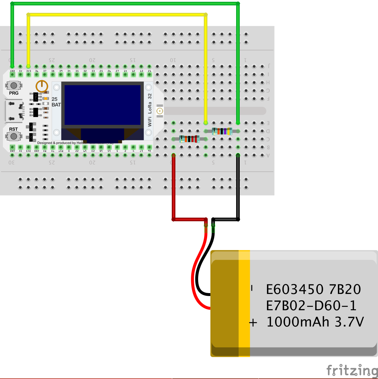

|
LoRa Battery Node.fzz | [31 KB] |
The LoRa power usage monitor sketch can be downloaded by clicking on the following link:

|
LoRaQuietBatteryPacketSender.zip | [3 KB] |
Update: 28 May 2023 Note that all current Heltec dev-boards include internal circuitry for monitoring battery voltage. This subject is discussed elsewhere on this site.
Heltec Wireless Stick Lite
Heltec Wireless Stick Lite modules are currently configured to monitor a rain gauge and water tank level. At the moment, neither is actually connected to a sensor and preset values are simply transmitted for testing purposes. The intent would ultimately be to use just a single sketch for each processor type, with appropriate configuration files to differentiate individual nodes and/or applications.
Update: 23 Mar 2023 Again, the following sketches are not compatible with the V3 Heltec Wireless Stick Lite board. The V3 board, and presumably future upgrades, are based on the newer ESP32-S3 processor and SX1262 LoRa node chip. Software compatible with the V3 boards is available elsewhere on this site.
The relevant sketches can be downloaded by clicking on the following links:

|
LoRaStickRainfallPacketSender.zip | [3 KB] |

|
LoRaStickTankPacketSender.zip | [3 KB] |
Heltec CubeCell [Plus]
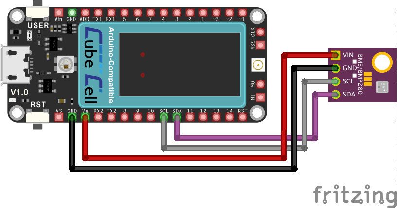
The Heltec CubeCell and CubeCell Plus modules are currently configured to monitor BME and wind speed/direction sensors. The 'wind' CubeCell is not actually connected to a sensor at this time and preset values are simply transmitted for testing purposes. The 'weather' CubeCells report actual data from BME280 sensors (configured per details below), but again, only preset values for rainfall and wind data.
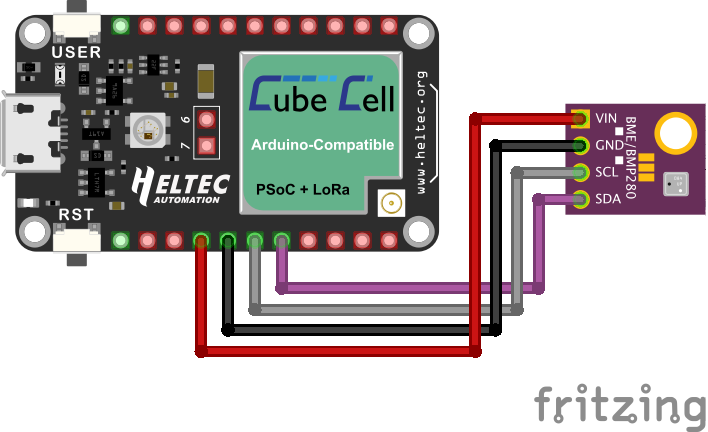
|
|

|
CubeCell BME I2C.fzz | [67 KB] |

|
CubeCell Plus BME I2C.fzz | [72 KB] |
Pin Configuration
| CubeCell | CubeCell Plus | BME |
|---|---|---|
| GND | GND | GND |
| VEXT | VEXT | VIN |
| SCL (Pin 28) | SCL (Pin 39) | SCL |
| SDA (Pin 29) | SDA (Pin 40) | SDA |
The code here is still pretty rough. I started out simply hacking the Heltec 'pingpong' example, but have since modified one of their more recent LoRa Sender example sketches to try to bring some of the low power elements of the processor into play. This was initially all just about getting the CubeCell to communicate with the WiFi LoRa 32 gateway, and subsequently the Pi Zero configuration, but I'm now moving on to getting the module to work comfortably on a solar panel/battery configuration.
One change that has occurred since I began working with the CubeCell is that there has been a significant upgrade of the Arduino IDE board hardware library. Earlier versions of the sketches provided below will not work with the latest revision of the Heltec CubeCell board software (1.2.0). Heltec also recommends upgrading to the latest version of the Arduino IDE (1.8.13 at the time of writing) before installing the latest board software (through the IDE Boards Manager or from the GitHub repository, although Heltec recommends the latter as it is updated more regularly).
The current CubeCell sketches (also OK on the CubeCell Plus if using the default I2C SCL/SDA pins), which do now use the CubeCell lowPowerHandler, can be downloaded by clicking on the following links.
These have not yet been incorporated into the 'package' referenced above as I have not tested everything with the new libraries required to support this code. Everything should be OK, but I have had to update these sketches on three occasions already, simply to deal with changes in function calls and variable definitions within the Heltec CubeCell hardware support software. I usually only find out about these changes when someone tries to use these sketches after an update. So, if you do hit a problem with any of the sketches, please let me know (post a note on the Forum).

|
LoRaCubeLowPowerWeatherPacketSender.zip | [5 KB] |

|
LoRaCubeLowPowerWindPacketSender.zip | [5 KB] |
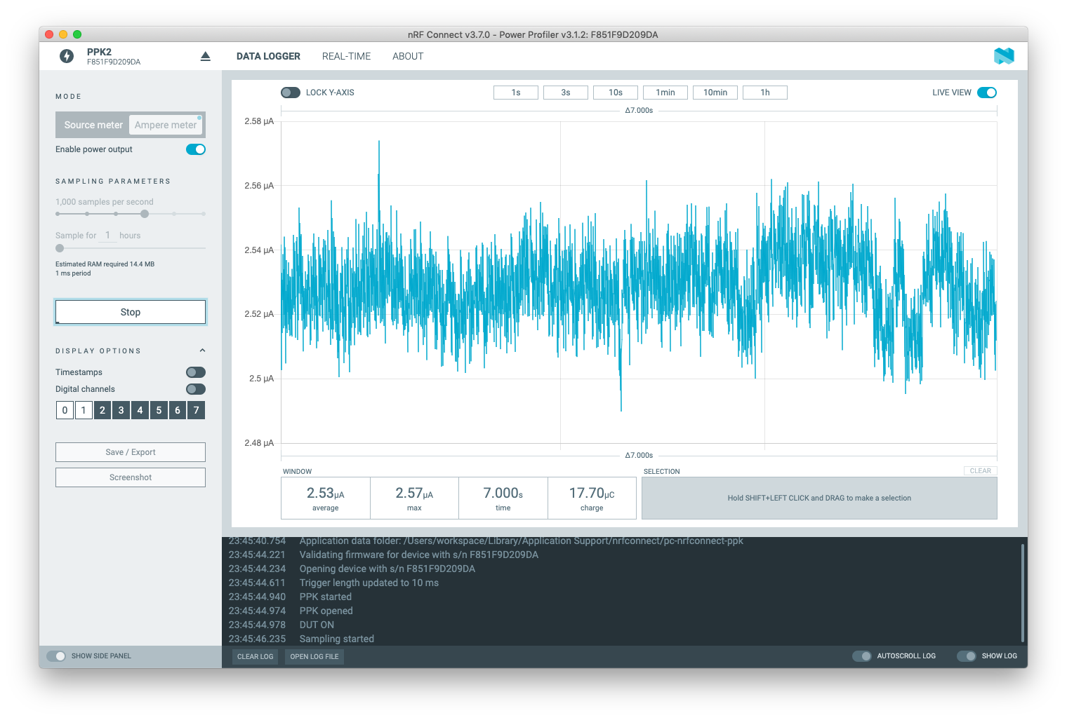
The most recent update to these sketches is dated 7 Aug 2021. Previous versions of the BME configuration (Weather Packet Sender) did not fully shut down in low power mode. Both of the sketches above (i.e. regardless of whether or not the BME280 sensor is connected) now draw less than 3µA when in low power mode. This level can generally be achieved if care is taken to turn off the radio (Radio.Sleep()) and external power (digitalWrite(Vext, HIGH)) before sleeping.
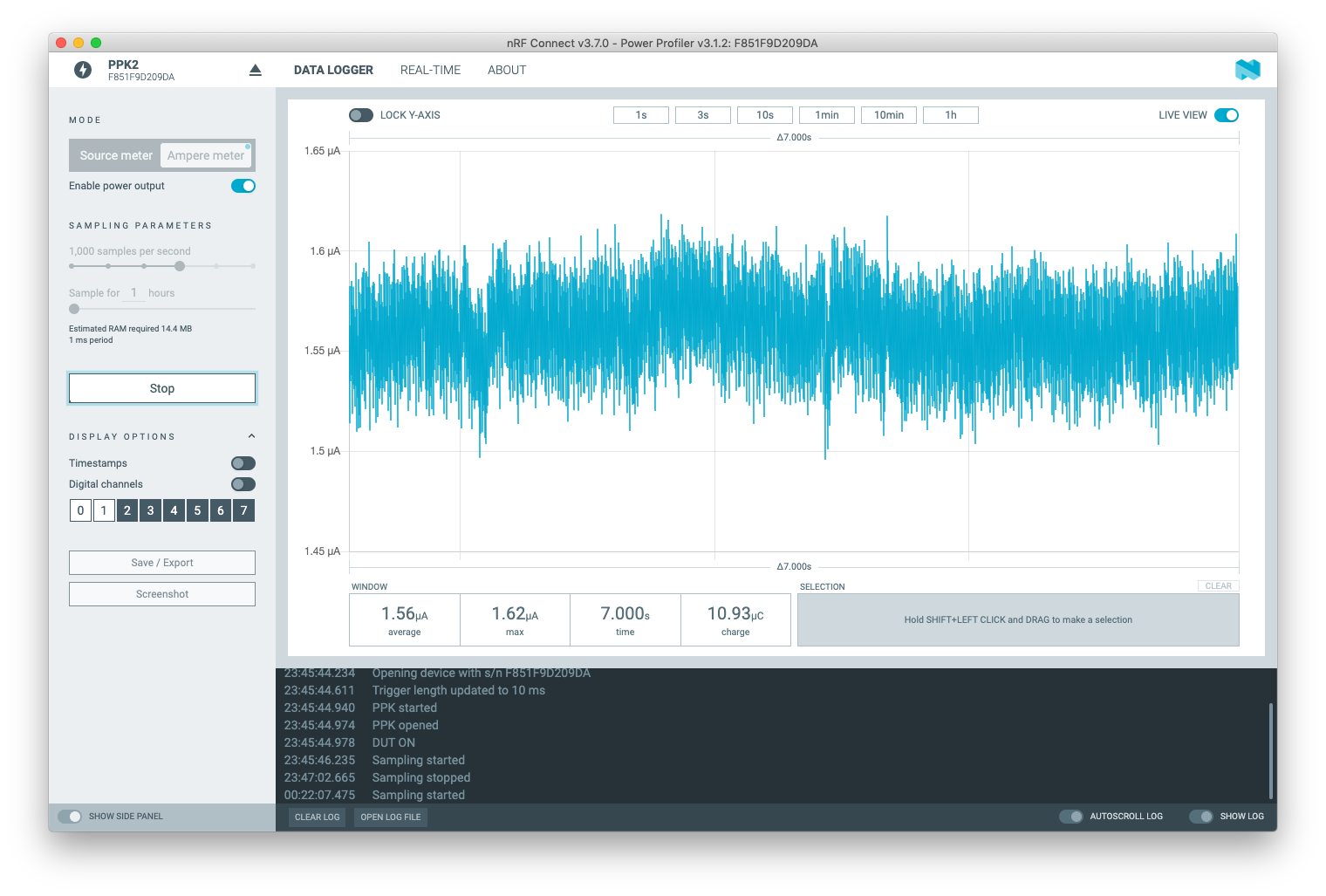
All of my power/sensor prototyping boards include a tapping point to allow the measurement of current in the power circuit and I use a Nordic Semiconductor PPK2 for this purpose.

Typical power profile when transmitting (two packets in sequence):

Typical power profile when sleeping:
The Heltec CubeCell processors are looking like a very attractive solution in their own right. It's still a relatively new product, with a relatively unique architecture, so the necessary software is still a little immature at the time of writing. But at currently around US$12 for a board with an inbuilt IoT band radio transceiver and LoRaWAN support, Li battery and solar power management, and claimed current draw of 3.5μA in deep sleep, it won't be easy to create an alternative hardware platform that is price-competitive.
Update: 22 May 2022 I now have two CubeCell Dev-Board Plus nodes running 'real' applications, [the beginnings of] a weather station (anemometer, rain collector & BME280) and an aerated wastewater treatment system (AWTS) monitor (line air pressure & ultrasonic distance measurement of tank water level). I've not yet documented these applications in their entirety, but some of the details relating to sensor configurations and packaging are provided under Node Hardware > Assembly > Sensors.
Elecrow ESP32S WiFi/BLE Board
The Elecrow ESP32S WiFi/BLE Boards are currently configured, along with an external RFM95W radio module, to monitor BME atmospheric sensors per the illustration below. The use of two I2C buses as illustrated is not really necessary (see the NodeMCU configuration below), I was just testing a range of configuration options at the time.
.png)

|
ESP32 BME OLED LoRa Sender (Breadboard).fzz | [296 KB] |
Pin Configuration
| ESP32S | OLED | BME | RFM95W |
|---|---|---|---|
| GND | GND | GND | GND |
| 3V3 | VDD | 3.3V | 3V3 |
| GPIO21 | SDA | ||
| GPIO22 | SCL | ||
| GPIO16 | SDA | ||
| GPIO17 | SCK | ||
| GPIO19 | MISO | ||
| GPIO23 | MOSI | ||
| GPIO18 | SCK | ||
| GPIO5 | NSS | ||
| GPIO14 | RESET | ||
| GPIO26 | DIO0 | ||
| GPIO33 | DIO1 | ||
| GPIO32 | DIO2 |
The relevant sketch and associated files can be downloaded by clicking on the following link:

|
LoRaESP32BMEPacketSender.zip | [28 KB] |
Amica NodeMCU DevKit
The Amica NodeMCU DevKit Boards are currently configured, along with an external RFM95W radio module, to monitor BME atmospheric sensors per the illustration below.
.png)

|
ESP8266 BME OLED LoRa Sender (Breadboard).fzz | [126 KB] |
Pin Configuration
| NodeMCU | OLED | BME | RFM95W |
|---|---|---|---|
| GND | GND | GND | GND |
| 3V3 | VDD | 3.3V | 3V3 |
| D2 | SDA | SDA | |
| D1 | SCK | SCL | |
| D6 | MISO | ||
| D7 | MOSI | ||
| D5 | SCK | ||
| D8 | NSS | ||
| D3 | RESET | ||
| SD3 | DIO0 |
The relevant sketch and associated files can be downloaded by clicking on the following link:

|
LoRaESP8266BMEPacketSender.zip | [28 KB] |
Arduino Pro Mini
The Arduino Pro Mini (3.3V) modules are currently configured, along with an external RFM95W radio module using the Wijnand Nijs PCB, to monitor BME atmospheric sensors.

The physical configuration is as illustrated below. In this case, I used a generic BME sensor module with the Adafruit libraries, rather than the SparkFun sensors and library used in the two previous configurations, again just to test different hardware configurations.
.png)

|
Pro Mini BME LoRa Sender (Breadboard).fzz | [126 KB] |
Pin Configuration
| Pro Mini | BME | RFM95W |
|---|---|---|
| GND | GND | GND |
| Vcc | 3.3V | 3V3 |
| A4 | SDA | |
| A5 | SCL | |
| 12 | MISO | |
| 11 | MOSI | |
| 13 | SCK | |
| 6 | NSS | |
| 5 | RESET | |
| 2 | DIO0 | |
| 3 | DIO1 | |
| 4 | DIO2 |
I did attempt to add an OLED display to the above configuration but, without having spent a great deal of time sorting out the precise details, it seems that the Pro Mini just doesn't have sufficient memory to support both an OLED display and a BME sensor while running my code. This was not a serious problem in the present case, as the Pro Mini configuration was being considered specifically for its ability to operate in a low power mode, with minimal load, so the use of a display of any sort was never a 'real-world' consideration.
Update: 14 June 2022 In creating a common code base that would compile on all of the hardware platforms I am using, I discovered the F() compiler macro, which can be used to instruct the compiler to store string constants in Flash memory, rather than SRAM, freeing up space in SRAM for program variables. This, apparently, is particularly relevant for the ATmega328P architecture and it may be that judicious use of the F() macro would free up enough SRAM to allow an OLED display to be configured, although I have not attempted to verify this proposition.
I have now built several Pro Mini-based nodes, in various configurations. Some of the nodes are configured to transmit full 'weather' reports (including rainfall and wind direction and speed), but the additional sensors are not currently connected or read (preset values are simply transmitted). The relevant sketches and associated files can be downloaded by clicking on the following links:

|
LoRaMiniBMEPacketSender.zip | [6 KB] |

|
LoRaMiniWeatherPacketSender.zip | [5 KB] |
When used in conjunction with the BCS-A4a sensor/power board, configured with a TPL5111 timer and TPS22860 power switch (or the MIC5219 regulator), and the following sketch, this configuration consumes 1.5–1.6µA while sleeping, without any other board modifications.

|
LoRaMiniBME-BCSA4a-PacketSender.zip | [6 KB] |
Typical power profile when transmitting (three packet sequence):
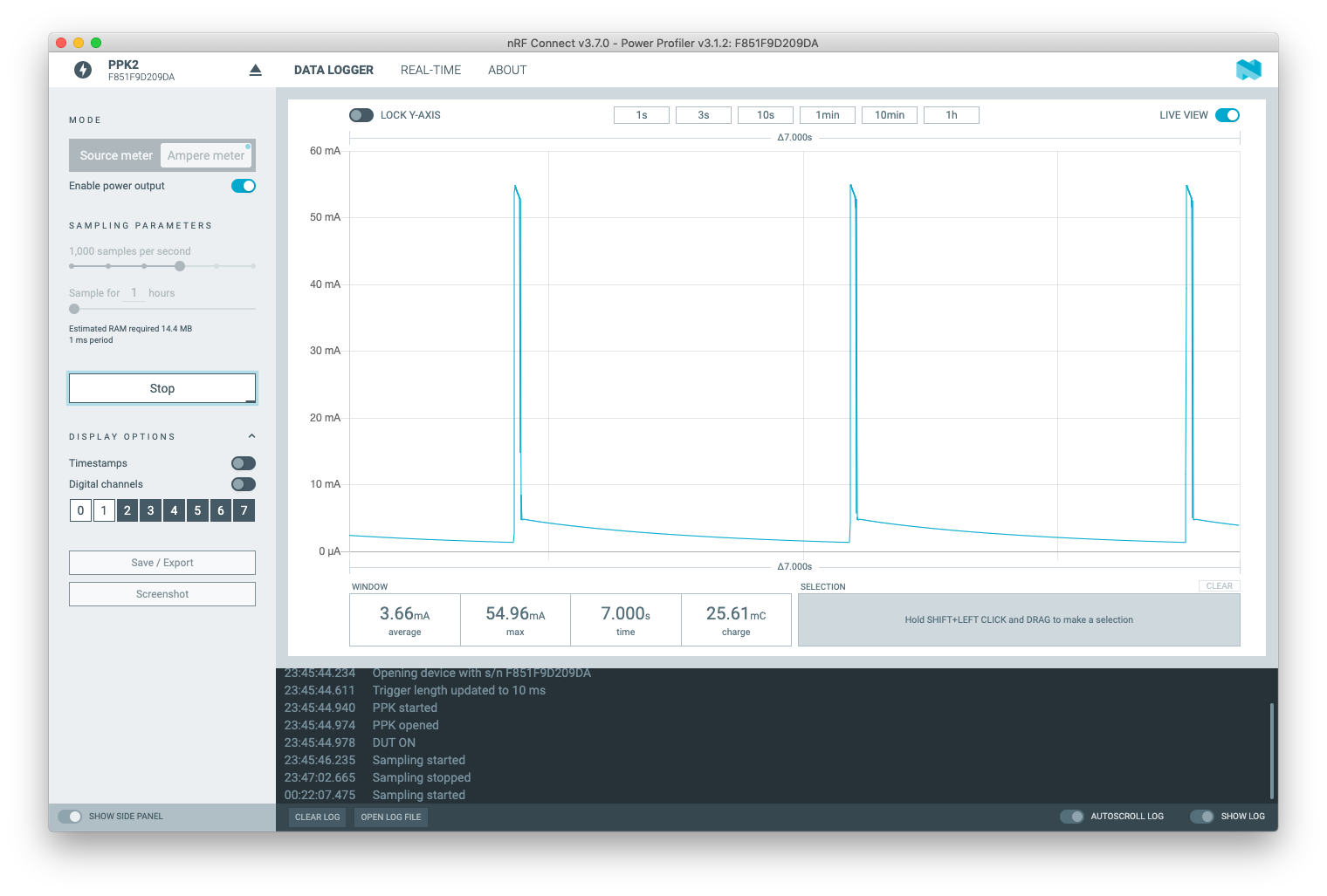
Typical power profile when sleeping:
