

13095-BPHC Test Procedures
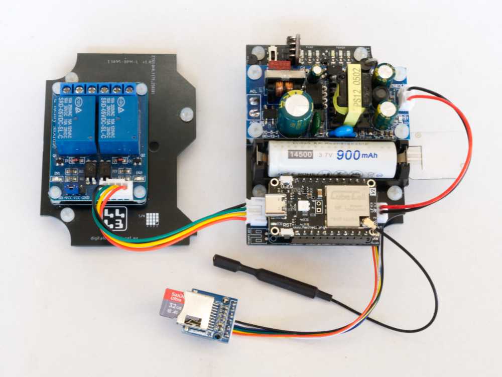
Refer to the 13095-BPHC PCB Assembly page for PCB and assembly details.
I took a different approach to testing this board. I had previously developed individual sketches to test the various elements of a board, with a view to being able to run these sketches on a range of processors in a range of application settings. In the present case, a single, more interactive sketch that allows the user to test all elements on this specific board was created. This approach led to the development of discrete modules, within this single sketch, to target the individual hardware elements of interest, the intent being to be able to simply drop these code segments into subsequent test and application sketches.
Test Modules
The sketch described herein includes code segments to test the following, generally hardware elements of the 13095-BPHC board:
- ACS712 sensor
- BME280 sensor
- Battery voltage
- DS18B20 sensor
- EEPROM read
- Flow sensor
- Interrupts—Local/Remote Mode Button press/release
- LoRa messaging
- Local/Remote Mode Control LED, through PCA9536
- CubeCell NeoPixel
- PCA9536 GPIO Port Expander
- Relay control and ON/OFF status LEDs, through PCA9536
- I2C Bus scan
- SD Card read/write
- Display software revision levels
- Vext control and Vext LED
- Watchdog timer operation
I run the test sketch through the Arduino IDE, entering commands via the Serial Monitor.
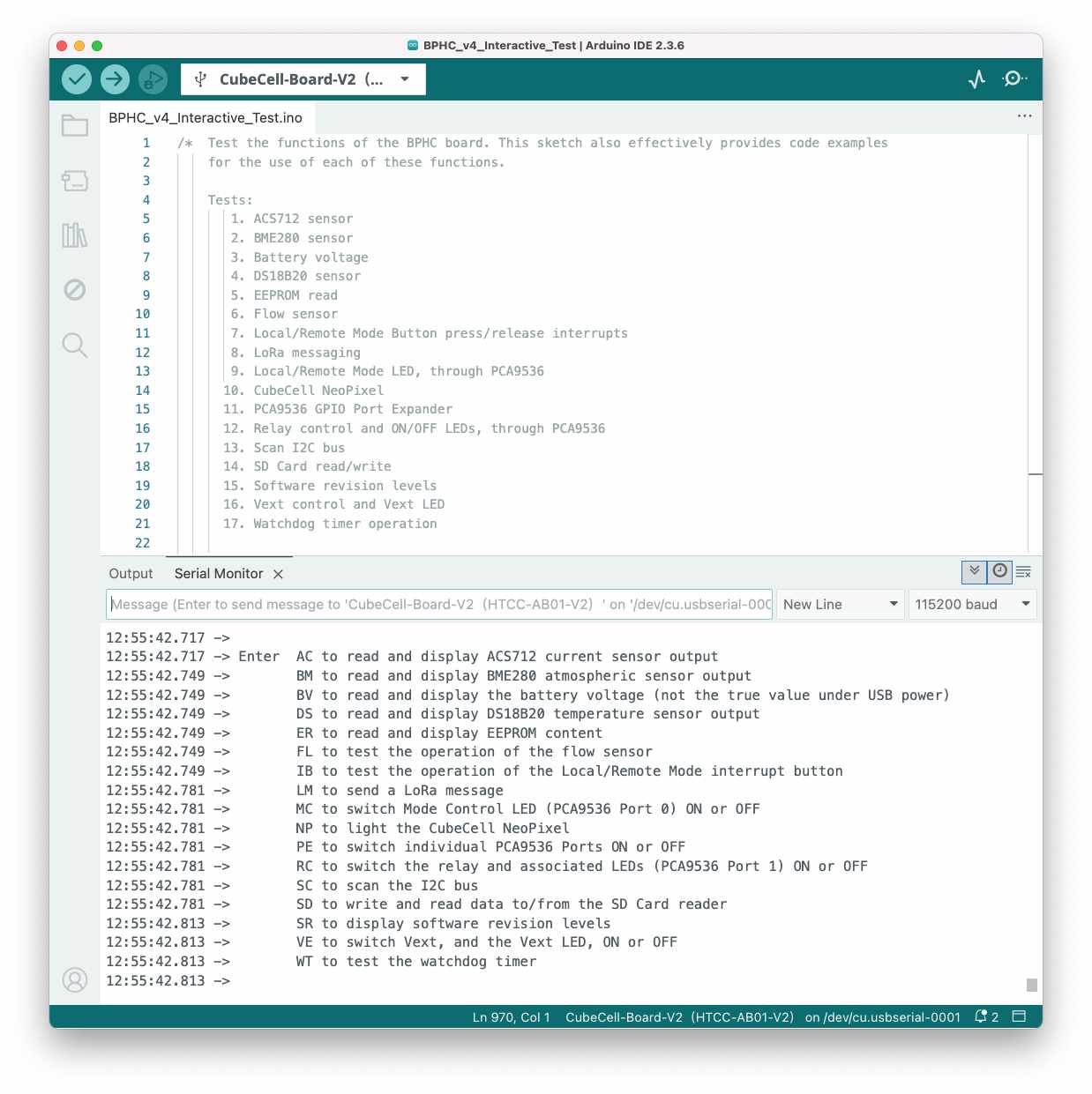
Individual tests are run in response to the relevant command, one at a time, in any sequence, as often as might be desired, although most components are powered through the Vext pin and thus require Vext to be ON for their testing to succeed. The Node will also continue to be reset when the watchdog timer expires if the watchdog timer test has not been run and an appropriate 'feeding' interval set.
The full code of the test sketch is presented below, primarily to provide the context for the code segments that follow in the discussion of individual tests.
/*  Test the functions of the BPHC board. This sketch also effectively provides code examples
    for the use of each of these functions.

    Tests:
       1. ACS712 sensor
       2. BME280 sensor
       3. Battery voltage
       4. DS18B20 sensor
       5. EEPROM read
       6. Flow sensor
       7. Local/Remote Mode Button press/release interrupts
       8. LoRa messaging
       9. Local/Remote Mode LED, through PCA9536
      10. CubeCell NeoPixel
      11. PCA9536 GPIO Port Expander
      12. Relay control and ON/OFF LEDs, through PCA9536
      13. Scan I2C bus
      14. SD Card read/write
      15. Software revision levels
      16. Vext control and Vext LED
      17. Watchdog timer operation

    EEPROM content is written independently using the ResetEEPROM_EH.ino sketch.

    24 May 2025 1.0.0 Base release
    26 May 2025 1.1.0 Refactor input processing code (processInput())
    27 May 2025 1.1.1 Improve consistency in variable naming and comments, and general tidy up
    06 Feb 2026 1.2.0 Add general PCA9536 test and identify specific ports for Mode and Relay tests
    08 Mar 2026 1.3.0 Add Flow sensor test framework (actual test code to follow)
    10 Mar 2026 1.3.1 Various minor wording/naming updates
    29 Mar 2026 1.3.2 Add ACS712 test

    29 Mar 2026
    Digital Concepts
    www.digitalconcepts.net.au
*/

#include <CubeCell_NeoPixel.h>  // CubeCell NeoPixel control library
#include <ACS712.h>             // Tillaart Library
#include <OneWire.h>            // OneWire bus
#include <DallasTemperature.h>  // DS18B20
#include <Wire.h>               // I2C bus
#include <Seeed_BME280.h>       // BME280
#include <SPI.h>                // SPI bus
#include <SD.h>                 // SD Card reader
#include <LoRa_APP.h>           // LoRa

#include "LangloLoRa.h"         // LoRa configuration parameters
#include "EepromHandler.h"      // EEPROM Handler class with access methods
#include "PacketHandler.h"      // Packet Handler class with access methods

//#include "CubeCellPins.h"
#include "CubeCellV2Pins.h"

// BPHC-specific pin definitions
#define WDT_DONE       GPIO0   // Watchdog Timer Done signal
#define ONE_WIRE_BUS   GPIO1   // DS18B20 OneWire bus
#define MODE_BUTTON    GPIO2   // Interrupt button on BPHC PCB
#define SPI_SD_CS      GPIO3   // SD Card reader SPI CS
//                     GPIO4   // CubeCell NeoPixel
#define FLOW_SIGNAL    GPIO5   // Flow sensor signal

// Sketch revision level
struct softwareRevision {
  const uint8_t major;			// Major feature release
  const uint8_t minor;			// Minor feature enhancement release
  const uint8_t minimus;		// 'Bug fix' release
};
softwareRevision sketchRevision = {1,3,2};

// The following are the Serial Monitor inputs that will be recognised
const String Test_Current   = "AC"; // ACS712 current sensor
const String Test_BME280    = "BM"; // BME280 atmospheric sensor
const String Test_Voltage   = "BV"; // Battery Voltage
const String Test_DS18B20   = "DS"; // DS18B20 temperature sensor
const String Test_EEPROM    = "ER"; // EEPROM Read
const String Test_Flow		  = "FL"; // Flow sensor
const String Test_Interrupt = "IB"; // Interrupt Button
const String Test_LoRa      = "LM"; // LoRa Message
const String Test_Mode      = "MC"; // Local/Remote Mode Control
const String Test_Neo       = "NP"; // CubeCell NeoPixel
const String Test_PCA9536   = "PE"; // PCA9536 Port Expander
const String Test_Relay     = "RC"; // Relay Control
const String Test_Scan      = "SC"; // Scan the I2C bus
const String Test_SDCard    = "SD"; // SD Card reader operation
const String Test_Revision  = "SR"; // Software Revision levels
const String Test_Vext      = "VE"; // Vext control
const String Test_WatchDog  = "WT"; // Watchdog Timer
const String returnChar     = "";   // Carriage Return

const String ON_State       = "ON";
const String OFF_State      = "OF";
const String Delete_Option  = "D";
const String Exists_Option  = "E";
const String Read_Option    = "R";
const String Write_Option   = "W";

String inputString;

// ACS712 current sensor
float signalFrequency = 50.0;			// 50Hz
uint16_t sampleCycles = 5;			// Sampling cycles
float acsSensitivity = 100.0;			// ACS712ELCTR-20A-T 100mv/A
uint16_t adcResolution = 4095;	// 12-bit resolution
float adcMaximumVoltage = 2.4;	// 2.4V

// Voltage Divider - The following brings 5V back to 3V so that 2.4V at the ADC would
//                   represent a current of 12A

const int R1 = 100;
const int R2 = 220;
float voltageDividerFactor = (R1 + R2)/float(R2);  // Set to (R1 + R2)/R2

float adcCurrent;

ACS712  acs712Sensor(ADC, adcMaximumVoltage, adcResolution, acsSensitivity);

// BME280 atmospheric sensor
const uint8_t I2C_BME280_Address[]  = {0x76,0x77};

uint16_t humidity = 0;
uint16_t pressure = 0;
int16_t temperature = 0;

BME280 bme280;

// CubeCell battery voltage measurement
  // Nothing special here

// DS18B20 temperature sensor
#define TEMPERATURE_PRECISION 9

int nodeTemperature = 0;

OneWire oneWire(ONE_WIRE_BUS);
DallasTemperature ds18b20Sensor(&oneWire);

// EEPROM
const uint8_t I2C_EEPROM_Address    = 0x50;

bool smartSerial = false;       // Smart Serial Addressing required for 32K and 64K EEPROMs

uint32_t gatewayMAC = 0;
uint32_t nodeMAC = 0;
uint8_t* descriptor;
uint16_t sequenceNumber, rainfallCounter;
uint8_t tankId, pumpId;

EepromHandler eeprom;

// Flow sensor
  // Nothing special here at the moment

// Interrupt button
// Commentary on the subject suggests that variables used within an ISR should be declared as volatile
volatile bool pressFlag = false;
volatile bool releaseFlag = false;

// LoRa
static RadioEvents_t RadioEvents;
void onTxDone( void );
void onTxTimeout( void );
int16_t rssi,rxSize;

uint16_t messageCounter = 0;

PacketHandler packet;

// Local/Remote Mode Control status LED (PCA9536)
	// See PCA9536
byte modeLedState = 0;

// NeoPixel
typedef enum {
  NP_OFF,
  NP_RED,
  NP_GREEN,
  NP_BLUE
} neoPixelColour_t;
// NeoPixel Parameters: # pixels, RGB or RGBW device, device colour order + frequency
CubeCell_NeoPixel neo(1, RGB, NEO_GRB + NEO_KHZ800);

// PCA9536 GPIO Port Expander
const uint8_t I2C_PCA9536_Address   = 0x41;
// PCA9536 registers
#define PCA9536_INPUT_PORT      0x00
#define PCA9536_OUTPUT_PORT     0x01
#define PCA9536_POLARITY_INV    0x02
#define PCA9536_CONFIG          0x03
// PCA9536 ports
#define PCA9536_PORT0_MASK      0x01
#define PCA9536_PORT1_MASK      0x02
#define PCA9536_PORT2_MASK      0x04
#define PCA9536_PORT3_MASK      0x08
// PCA9536 port states
#define PCA9536_PORT_STATE_ON   0xFF
#define PCA9536_PORT_STATE_OFF  0x00
// PCA9536 Port Functions
#define MODE_PORT								0x00
#define RELAY_PORT							0x01

// Relay control and status LEDs (PCA9536)
	// See PCA9536
byte relayLedState = 0;

// SD Card reader
  // Nothing special here

// Vext
bool vextOnFlag = false;

// Watchdog timer
uint16_t feedingInterval;
static TimerEvent_t watchdogFeeder;

void setup() {
  Serial.begin(115200);
  Serial.println("[setup] BPHC PCB Test Program");
  printSoftwareRevision();

  pinMode(Vext,OUTPUT);
  vextOff();
  pinMode(RELAY_CONTROL,OUTPUT);
  pinMode(SPI_SD_CS,OUTPUT);
  PINMODE_INPUT_PULLUP(MODE_BUTTON);

  RadioEvents.TxDone = onTxDone;
  RadioEvents.TxTimeout = onTxTimeout;

  Radio.Init( &RadioEvents );
  Radio.SetChannel( RF_FREQUENCY );
  Radio.SetTxConfig( MODEM_LORA, TX_OUTPUT_POWER, 0, LORA_BANDWIDTH,
                                 LORA_SPREADING_FACTOR, LORA_CODINGRATE,
                                 LORA_PREAMBLE_LENGTH, LORA_FIX_LENGTH_PAYLOAD_ON,
                                 true, 0, 0, LORA_IQ_INVERSION_ON, 3000 );
  Radio.Sleep( );

// Flow sensor
  pinMode(FLOW_SIGNAL,INPUT);

// SD Card reader
  pinMode(SPI_SD_CS,OUTPUT);

// Vext
  pinMode(Vext,OUTPUT);
  vextOn();
  // Let everyone know we're starting up...
  cycleNeoPixel();
  vextOff();

// Watchdog timer
/*
  The Watchdog Timer is used to 'feed' the watchdog at preset intervals. The watchdog
  must be fed more often that its [hardware] preset timeout interval. The feeding interval,
  <wdtLimit> milliseconds, can be set within the watchdog test sequence. By default, the
  'feeder' is inactive and the watchdog will reset the Node when its timeout interval expires.
*/
  pinMode(WDT_DONE,OUTPUT);
  TimerInit(&watchdogFeeder, feedTheDog);

  promptForInput();
}

void loop() {
  if ( Serial.available() > 0 ) {
    inputString = Serial.readString();
    Serial.print("[loop] Input string: ");
    Serial.println(inputString);
    processInput(inputString);
    promptForInput();
  }
}

// Sketch flow management

void promptForInput() {
  Serial.println();
  Serial.println("Enter  AC to read and display ACS712 current sensor output");
  Serial.println("       BM to read and display BME280 atmospheric sensor output");
  Serial.println("       BV to read and display the battery voltage (not the true value under USB power)");
  Serial.println("       DS to read and display DS18B20 temperature sensor output");
  Serial.println("       ER to read and display EEPROM content");
  Serial.println("       FL to test the operation of the flow sensor");
  Serial.println("       IB to test the operation of the Local/Remote Mode interrupt button");
  Serial.println("       LM to send a LoRa message");
  Serial.println("       MC to switch Mode Control LED (PCA9536 Port 0) ON or OFF");
  Serial.println("       NP to light the CubeCell NeoPixel");
  Serial.println("       PE to switch individual PCA9536 Ports ON or OFF");
  Serial.println("       RC to switch the relay and associated LEDs (PCA9536 Port 1) ON or OFF");
  Serial.println("       SC to scan the I2C bus");
  Serial.println("       SD to write and read data to/from the SD Card reader");
  Serial.println("       SR to display software revision levels");
  Serial.println("       VE to switch Vext, and the Vext LED, ON or OFF");
  Serial.println("       WT to test the watchdog timer");
  Serial.println();
}

void processInput( String inputString ) {

  int stringLength = inputString.length();
  String upperString = inputString;
  upperString.toUpperCase();

	//  Serial.println("[processInput] Skip leading white space...");
  int i = 0;
  while ( isspace(upperString[i]) ) i++;
	//  Serial.println("[processInput] Process command...");
  if ( i + 2 < stringLength ) {
		String command = upperString.substring(i,i+2);
    i = i+2;
		if ( command == Test_Current ) {
	//    Serial.println("Identifier is AC");
			readACS712Sensor();
		} else if ( command == Test_BME280 ) {
	//    Serial.println("Identifier is BM");
			readBME280Sensor();
		} else if ( command == Test_Voltage ) {
	//    Serial.println("Identifier is BV");
			readBatteryVoltage();
		} else if ( command == Test_DS18B20 ) {
	//    Serial.println("Identifier is DS");
			readDS18B20Sensor();
		} else if ( command == Test_EEPROM ) {
	//    Serial.println("Identifier is ER");
			readEepromContent();
		} else if ( command == Test_Flow ) {
	//    Serial.println("Identifier is FL");
			readFlowSensor();
		} else if ( command == Test_Interrupt ) {
	//    Serial.println("Identifier is IB");
			// Get number of cycles and long press duration from input string.
      // If none specified, cycles defaults to 5 and longPressDuration to 1000 miliseconds.
			int cycleCount = 5;
      unsigned long longPressDuration = 1000;
			while ( !isdigit(upperString[i]) && i < stringLength ) i++;
			if ( i < stringLength ) {
				int j = i;
				while ( isdigit(upperString[j]) && j < stringLength ) j++;
				cycleCount = upperString.substring(i,j).toInt();
				int k = j;
        while ( !isdigit(upperString[k]) && k < stringLength ) k++;
        if ( k < stringLength ) {
          int l = k;
          while ( isdigit(upperString[l]) && l < stringLength ) l++;
          longPressDuration = upperString.substring(k,l).toInt();
        }
			}
			processInterrupts(cycleCount,longPressDuration);
		} else if ( command == Test_LoRa ) {
	//    Serial.println("Identifier is LM");
			while ( isspace(upperString[i]) ) i++;
			if ( i < stringLength ) {
				// Provide any appropriate options...
			} else {
				// Just send a Reset packet
				Serial.println("[Test_LoRa] Sending packet, Reset Code 99...");
				sendLoraMessage();
			}
		} else if ( command == Test_Mode ) {
	//    Serial.println("Identifier is MC");
			int port = 0;
			while ( isspace(upperString[i]) ) i++;
			if ( i < stringLength ) {
				if ( isdigit(upperString[i]) ) {
					port = upperString.substring(i,i+1).toInt();
					if ( port > 3 ) {
						Serial.println("[Test_Mode] Port must be in the range 0..3");
					} else {
						i++;
						while ( isspace(upperString[i]) ) i++;
						if ( i < stringLength ) {
							String state = upperString.substring(i,i+2);
							if ( state == ON_State ) {
								pcaPortOn(port);
							} else if ( state == OFF_State ) {
								pcaPortOff(port);
							} else {
								Serial.println("[Test_Mode] State not recognised - Command format: MC <port #> <ON/OFF>");
							}
						} else {
							Serial.println("[Test_Mode] No State entered - Command format: MC <port #> <ON/OFF>");
						}
					}
				} else {
					Serial.println("[Test_Mode] Command format: MC <port #> <ON/OFF>");
				}
			} else {
				Serial.println("[Test_Mode] Command format: MC <port #> <ON/OFF>");
			}
		} else if ( command == Test_Neo ) {
	//    Serial.println("Identifier is NP");
			while ( isspace(upperString[i]) ) i++;
			if ( i < stringLength ) {
				// See what colour they want...
				// Create an array of colours to search for
				String colours[] = {"RED", "GREEN", "BLUE", "OFF"};
				// Initialize minimum position with a value larger than string length
				int minPos = stringLength + 1;
				String foundColour = "";
				// Search for each colour
				for (String colour : colours) {
						int pos = upperString.indexOf(colour);
						if (pos != -1 && pos < minPos) {
								minPos = pos;
								foundColour = colour;
						}
				}
				if ( foundColour.length() > 0 ) {
					if ( foundColour == "RED" ) {
						Serial.println("[Test_Neo] NeoPixel RED...");
						neoPixel(NP_RED);
					} else if ( foundColour == "GREEN" ) {
						Serial.println("[Test_Neo] NeoPixel GREEN...");
						neoPixel(NP_GREEN);
					} else if ( foundColour == "BLUE" ) {
						Serial.println("[Test_Neo] NeoPixel BLUE...");
						neoPixel(NP_BLUE);
					} else {
						Serial.println("[Test_Neo] NeoPixel OFF...");
						neoPixel(NP_OFF);
					}
				} else {
					Serial.println("[Test_Neo] Usage : NP RED/GREEN/BLUE/OFF");
				}
			} else {
				// Just cycle the NeoPixel through the three primaries
				Serial.println("[Test_Neo] Cycling NeoPixel...");
				cycleNeoPixel();
				Serial.println("[Test_Neo] Cycle complete");
			}
		} else if ( command == Test_Relay ) {
	//    Serial.println("Identifier is RC");
			while ( isspace(upperString[i]) ) i++;
			String state = upperString.substring(i,i+2);
			if ( state == ON_State ) {
				Serial.println("[Test_Relay] Relay ON");
				digitalWrite(RELAY_CONTROL,HIGH);     // Turn on the external power supply
			} else if ( state == OFF_State ) {
				Serial.println("[Test_Relay] Relay OFF");
				digitalWrite(RELAY_CONTROL,LOW);     // Turn off the external power supply
			} else {
				Serial.println("[Test_Relay] Command not recognised, use ON or OFF");
			}
		} else if ( command == Test_Scan ) {
	//    Serial.println("Identifier is SC");
			uint8_t deviceAddress;
			int k = inputString.indexOf("0x");
			if (k < 0) {
				Serial.println("[Test_Scan] No hex prefx found, check for a decimal number...");
				// No HEX prefix found, so just look for a string of [decimal] digits
				while ( !isdigit(inputString[i]) && i < stringLength ) i++;
				if ( i < stringLength ) {
					int j = i;
					while ( isdigit(inputString[j]) && j < stringLength ) j++;
					Serial.print("[Test_Scan] Found : ");
					Serial.println(inputString.substring(i,j));
					deviceAddress = inputString.substring(i,j).toInt();
					scanI2cBus(deviceAddress);
				} else {
					Serial.println("[Test_Scan] No address found, just scan the bus");
					scanI2cBus(0);
				}
			} else {
				// Parse out the HEX digits
				Serial.println("[Test_Scan] Parsing hex string...");
				i = k + 2;
				int j = i;
				while (isHexadecimalDigit(inputString[j]) && j < stringLength ) j++;
				String hexString = inputString.substring(i,j);
				deviceAddress = strtoul(hexString.c_str(),0,16);
				Serial.print("[Test_Scan] Found : 0x");
				Serial.println(inputString.substring(i,j));
				scanI2cBus(deviceAddress);
			}
		} else if ( command == Test_SDCard ) {
	//    Serial.println("Identifier is SD");
			while ( isspace(upperString[i]) ) i++;
			if ( i < stringLength ) {
				String option = upperString.substring(i,i+1);
				if ( option == Delete_Option ) {
					deleteSdCardFile();
				} else if ( option == Exists_Option ) {
					existsSdCardFile();
				} else if ( option == Read_Option ) {
					readSdCardFile();
				} else if ( option == Write_Option ) {
					writeSdCardFile();
				} else {
					Serial.println("[Test_SDCard] Command option not recognised, use [D]elete, [E]xists, [R]ead or [W]rite");
				}
			} else {
				// Just display the SD card specs
				getSdCardInfo();
			}
		} else if ( command == Test_Revision ) {
	//    Serial.println("Identifier is SR");
			printSoftwareRevision();
		} else if ( command == Test_Vext ) {
	//    Serial.println("Identifier is VC");
			while ( isspace(upperString[i]) ) i++;
			String state = upperString.substring(i,i+2);
			if ( state == ON_State ) {
				vextOn();     // Turn on the external power supply
			} else if ( state == OFF_State ) {
				vextOff();    // Turn off the external power supply
			} else {
				Serial.println("[Test_Vext] Command not recognised, use ON or OFF");
			}
		} else if ( command == Test_WatchDog ) {
	//    Serial.println("Identifier is WT");
			while ( !isdigit(upperString[i]) && i < stringLength ) i++;
			if ( i < stringLength ) {
				int j = i;
				while ( isdigit(upperString[j]) && j < stringLength ) j++;
				feedingInterval = upperString.substring(i,j).toInt();
				setWatchdogFeeder(feedingInterval);
			} else {
				Serial.println("[Test_WatchDog] The watchdog timeout is set in hardware, via the resistance set through trimpot R15.");
				Serial.println("                We need to feed the dog regularly, before the timeout timer expires. If we let this");
				Serial.println("                program run for several minutes, the processor will reset when the timer expires. If");
				Serial.println("                we note the time interval between resets, we can determine how often we need to feed");
				Serial.println("                the dog. The feeding interval, specified in milliseconds, should be less than the");
				Serial.println("                timeout interval by some appropriate 'safety' margin.");
				Serial.println("                To set a feeding interval, enter: WD <interval>");
				Serial.println();
				if ( feedingInterval == 0 ) {
					Serial.println("[Test_WatchDog] No feeding interval is currently set");
				} else {
					Serial.print("[Test_WatchDog] The feeding interval is currently set at ");
					Serial.print(feedingInterval);
					Serial.println(" seconds");
				}
			}
		}
  } else {
  	Serial.println("[processInput] Command not recognised...");
  }
}

bool isHexadecimalDigit( char character ) {
  return  ( character >= '0' && character <= '9') ||
          ( character >= 'A' && character <= 'F') ||
          ( character >= 'a' && character <= 'f');
}

// ACS712

void readACS712Sensor() {

// ACS712 Current Sensor
  Serial.println("[readACS712Sensor] Set sample MidPoint...");
  acs712Sensor.autoMidPoint(signalFrequency,sampleCycles);
  Serial.print("[readACS712Sensor] MidPoint : ");
  Serial.println(acs712Sensor.getMidPoint());
  Serial.print("                   Noise mV : ");
  Serial.println(acs712Sensor.getNoisemV());
  Serial.println("[readACS712Sensor] Display sensor reading...");
  adcCurrent = acs712Sensor.mA_AC_sampling(signalFrequency,sampleCycles) * voltageDividerFactor;
  Serial.print("[readACS712Sensor]       mA : ");
  Serial.println(adcCurrent);
}

// BME280

void readBME280Sensor() {
  bool OKtoGO = false;
  Serial.println("[readBME280Sensor] Read sensor...");
  delay(50);                  // Give everything a moment to settle down
  Wire.begin();               // On with the show...

  Serial.println("[readBME280Sensor] Check possible BME280 sensor addresses...");
  Serial.print("[readBME280Sensor] Try 0x");
  Serial.print(I2C_BME280_Address[0],HEX);
  Serial.println("...");
  if (bme280.init(I2C_BME280_Address[0])) {
    Serial.println("[readBME280Sensor] Sensor found");
    OKtoGO = true;
  } else {
    Serial.print("[readBME280Sensor] Try 0x");
    Serial.print(I2C_BME280_Address[1],HEX);
    Serial.println("...");
    if (bme280.init(I2C_BME280_Address[1])) {
      Serial.println("[readBME280Sensor] Sensor found");
      OKtoGO = true;
    } else {
      Serial.println( "[readBME280Sensor] Cannot find BME280 sensor, check Vext.=" );
    }
  }

  if (OKtoGO) {
    Serial.println( "[readBME280Sensor] BME280 sensor initialisation complete" );

	  delay(100); // The BME280 needs a moment to get itself together... (50ms is too little time)

	  temperature = (int) (10*bme280.getTemperature());
	  pressure = (int) (bme280.getPressure() / 91.79F);
	  humidity = (int) (bme280.getHumidity());

		Serial.println();
		Serial.print("[readBME280Sensor] Temperature: ");
		Serial.println((float) temperature/10, 1);
		Serial.print("[readBME280Sensor] Pressure: ");
		Serial.println(pressure);
		Serial.print("[readBME280Sensor] Humidity: ");
		Serial.println(humidity);
  }

  Wire.end();
}

// Battery voltage

void readBatteryVoltage() {
  uint16_t batteryVoltage = getBatteryVoltage();
  Serial.print("[readBatteryVoltage] Battery Voltage : ");
  Serial.print( batteryVoltage );
  Serial.println(" mV");
}

// DS18B20

void readDS18B20Sensor() {
  Serial.println("[readDS18B20Sensor] Read sensor...");
/*
 * If this node is reading atmospheric conditions from a BME sensor
 * All values recorded as integers, temperature multiplied by 10 to keep one decimal place
*/
  ds18b20Sensor.begin();
  delay(100);                 // Give everything a moment to settle down
  if ( ds18b20Sensor.getDeviceCount() > 0 ) {
    ds18b20Sensor.requestTemperatures(); // Send the command to get temperatures
    // After we got the temperatures, we can print them here.
    // We use the function ByIndex, and get the temperature from the first sensor only.
    float tempTemperature = ds18b20Sensor.getTempCByIndex(0);
    Serial.print("[readDS18B20Sensor] Returned value: ");
    Serial.println(tempTemperature);

    nodeTemperature = (int) (10*(tempTemperature + 0.05));

    Serial.print("[readDS18B20Sensor] Temperature: ");
    Serial.println((float) nodeTemperature/10, 1);
  } else {
    Serial.println("[readDS18B20Sensor] No sensor found, check Vext");
  }
}

// EEPROM

void readEepromContent() {
  Wire.begin();
  eeprom.begin(&Wire);
  if ( eeprom.isConnected() ) {
    printEepromContent();
  } else {
    Serial.println("[readEepromContent] EEPROM not found, check Vext");
  }
  Wire.end();
}

void printEepromContent() {
  smartSerial = eeprom.setSmartSerial();
  if (smartSerial) {
    Serial.println("[printEepromContent] Smart Serial Addressing (32K+ EEPROM)");
  } else {
    Serial.println("[printEepromContent] Standard Serial Addressing (16K- EEPROM)");
  }
  gatewayMAC = eeprom.readUint32(EH_GATEWAY_MAC);
  Serial.print(F("   Gateway MAC (GM): 0x"));
  Serial.println(gatewayMAC,HEX);
  nodeMAC = eeprom.readUint32(EH_NODE_MAC);
  Serial.print(F("      Node MAC (NM): 0x"));
  Serial.println(nodeMAC,HEX);
  Serial.print(F("    Descriptor (DS): "));
  descriptor = eeprom.readBytes(EH_DESCRIPTOR);
  int byteCount = eeprom.getParameterByteCount(EH_DESCRIPTOR);
  for (int i = 0; i < byteCount; i++) {
    Serial.print((char)descriptor[i]);
  }
  Serial.println();
  sequenceNumber = eeprom.readUint16(EH_SEQUENCE);
  Serial.print(F("    Sequence # (SN): "));
  Serial.println(sequenceNumber);
  rainfallCounter = eeprom.readUint16(EH_RAINFALL);
  Serial.print(F("  Rain Counter (RC): "));
  Serial.println(rainfallCounter);
  tankId = eeprom.readUint16(EH_TANKID);
  Serial.print(F("       Tank ID (TD): "));
  Serial.println(tankId);
  pumpId = eeprom.readUint16(EH_PUMPID);
  Serial.print(F("       Pump ID (PD): "));
  Serial.println(pumpId);
}

// Flow sensor

void readFlowSensor() {
  Serial.println("[readFlowSensor] Display sensor reading...");
  Serial.println("                 Coming soon...");
}

// Interrupts

void buttonPress() {
  pressFlag = true;
  attachInterrupt(digitalPinToInterrupt(MODE_BUTTON), buttonRelease, RISING);
//  Serial.println("Press ping!");
}

void buttonRelease() {
  releaseFlag = true;
  attachInterrupt(digitalPinToInterrupt(MODE_BUTTON), buttonPress, FALLING);
//  Serial.println("Release ping!");
}

void processInterrupts( uint8_t interruptCount, unsigned long longPressDuration ) {
  /* A button press pulls the interrupt pin to ground, so the leading edge  */
  /* of the interrupt will be falling, while the trailing edge is rising.   */
  Serial.print("[processInterrupts] Initiate interrupt test, ");
  Serial.print(interruptCount);
  Serial.print(" cycles with a long press duratiion of ");
  Serial.print(longPressDuration);
  Serial.println(" milliseconds...");
  Serial.println("[processInterrupts] Press the MODE button to generate an interrupt...");
  Serial.println();

  // Ultimately we want this section to also control the relevant LEDs and the relay
  // Long Press toggles between Local and Remote Modes, turning the Mode LED ON and OFF accordingly
  // Short Press toggles the relay, and ON/OFF LEDs, when in Local Mode

  bool pressProcess = false;
  bool releaseProcess = true;

  pressFlag = false;
  attachInterrupt(digitalPinToInterrupt(MODE_BUTTON), buttonPress, FALLING);
  unsigned long timeInterval;
  unsigned long thenTime = 0;
  unsigned long nowTime = 0;
  unsigned long debounceInterval = 200;
  int i = 0;
  while ( i < interruptCount ) {
    if ( pressFlag ) {
      if ( releaseProcess ) {
        Serial.println("[processInterrupts] Button press [FALLING interrupt] detected");
        thenTime = millis();
        timeInterval = thenTime - nowTime;
        Serial.print("[processInterrupts] nowTime : ");
        Serial.print(nowTime);
        Serial.print("   thenTime : ");
        Serial.print(thenTime);
        Serial.print("   Interval : ");
        Serial.print(timeInterval);
        if ( timeInterval < debounceInterval ) {
          Serial.println("  Bounce...");
          Serial.println("[processInterrupts] Bounce detected, reset interrupts...");
          Serial.println();
          delay(100);
          attachInterrupt(digitalPinToInterrupt(MODE_BUTTON), buttonPress, FALLING);
          releaseFlag = false;
          pressProcess = false;
          releaseProcess = true;
        } else {
          Serial.println();
          pressProcess = true;
          releaseProcess = false;
        }
      }
      pressFlag = false;
    }
    if ( releaseFlag ) {
      if ( pressProcess ) {
        Serial.println("[processInterrupts] Button release [RISING interrupt] detected");
        nowTime = millis();
        timeInterval = nowTime - thenTime;
        Serial.print("[processInterrupts] thenTime : ");
        Serial.print(thenTime);
        Serial.print("   nowTime : ");
        Serial.print(nowTime);
        Serial.print("   Interval : ");
        Serial.print(timeInterval);
        if ( timeInterval > longPressDuration ) {
          Serial.println("  Long Press...");
        } else {
          Serial.println("  Short Press...");
        }
        Serial.println();
        pressProcess = false;
        releaseProcess = true;
        i++;
      }
      thenTime = nowTime;
      releaseFlag = false;
    }
    /* For some reason, we have to have this trivial delay here. Without it, the above serial output  */
    /* never appears [when the relevant flags are set]. It's no good inside the if statement, and     */
    /*  it's no good if it's not here, but I'll be stuffed if I know why it's required...             */
    delay(1);
  }
  detachInterrupt( digitalPinToInterrupt(MODE_BUTTON));
  Serial.println("[processInterrupts] OK, next test.");
}

// LoRa

void onTxDone(void) {
  Radio.Sleep();
}
void onTxTimeout(void) {
  Radio.Sleep();
}

void sendLoraMessage() {
  packet.begin(gatewayMAC, nodeMAC, messageCounter);
  packet.setPacketType(RESET);
  packet.setResetCode(99);
  int totalByteCount = packet.packetByteCount();
  Serial.println("[sendLoraMessage] Finished Packet");
  neoPixel(NP_GREEN);   // NeoPixel [low intensity] GREEN
  Radio.Send((uint8_t *)packet.byteStream(), packet.packetByteCount());
  neoPixel(NP_OFF);    // NeoPixel OFF
  Serial.println("[sendLoraMessage] Packet Sent");
  Serial.println();
}

// Local/Remote Mode LED (see PCS9536)
  // Nothing special here

// NeoPixel

void neoPixel(neoPixelColour_t colour) {
  uint8_t red, green, blue;
  // RGB can be 0..255, but 255 is very bright
  switch ( colour ) {
    case NP_OFF: {
      red = 0;
      green = 0;
      blue = 0;
      break;
    }
    case NP_RED: {
      red = 32;
      green = 0;
      blue = 0;
      break;
    }
    case NP_GREEN: {
      red = 0;
      green = 32;
      blue = 0;
      break;
    }
    case NP_BLUE: {
      red = 0;
      green = 0;
      blue = 32;
      break;
    }
    default:
      break;
  }

	neo.begin();                                        // Initialise RGB strip object
	neo.clear();                                        // Set all pixel 'off'
	neo.setPixelColor(0, neo.Color(red, green, blue));  // The first parameter is the NeoPixel index, and we only have one
	neo.show();                                         // Send the updated pixel colors to the hardware.
}

void cycleNeoPixel () {
  if (vextOnFlag) {
    Serial.println("[cycleNeoPixel] RED...");
    neoPixel(NP_RED);     // NeoPixel [low intensity] RED
    delay(1000);
    Serial.println("[cycleNeoPixel] GREEN...");
    neoPixel(NP_GREEN);   // NeoPixel [low intensity] GREEN
    delay(1000);
    Serial.println("[cycleNeoPixel] BLUE...");
    neoPixel(NP_BLUE);    // NeoPixel [low intensity] BLUE
    delay(1000);
    neoPixel(NP_OFF);     // NeoPixel OFF
  } else {
    Serial.println("[cycleNeoPixel] Vext must be ON to run the NeoPixel test");
  }
}

// PCA9536, including Local/Remote Mode and Relay status LEDs

void pcaPortOn(uint8_t port) {
  Serial.print("[pcaPortOn] Switching output port ");
  Serial.print(port);
  Serial.println(" ON");

  // Initialize I2C
  byte result;
  Wire.begin();

  // Configure PCA9536 as outputs
  Wire.beginTransmission(I2C_PCA9536_Address);
  Wire.write(PCA9536_CONFIG);
  Wire.write(0x00); // 0x00 = all outputs
  result = Wire.endTransmission();

  if ( result == 0 ) {
    // Set polarity inversion to normal
    Wire.beginTransmission(I2C_PCA9536_Address);
    Wire.write(PCA9536_POLARITY_INV);
    Wire.write(0x00); // 0x00 = normal polarity
    Wire.endTransmission();

    switch ( port ) {
      case 0: {
        modeLedState = PCA9536_PORT0_MASK & PCA9536_PORT_STATE_ON;
        break;
      }
      case 1: {
        relayLedState = PCA9536_PORT1_MASK & PCA9536_PORT_STATE_ON;
        break;
      }
    }
    byte controlByte = modeLedState + relayLedState;
    Serial.print("[pcaPortOn] controlByte : ");
    Serial.println((int)controlByte, HEX);
    // Write to PCA9536
    Wire.beginTransmission(I2C_PCA9536_Address);
    Wire.write(PCA9536_OUTPUT_PORT);
    Wire.write(controlByte);
    Wire.endTransmission();
  } else {
    Serial.print("[pcaPortOn] Error : ");
    Serial.println(result);
    Serial.println("[pcaPortOn] PCA9536 not found, check Vext");
  }

  Wire.end();
}

void pcaPortOff(uint8_t port) {
  Serial.print("[pcaPortOff] Switching output port ");
  Serial.print(port);
  Serial.println(" OFF");

  byte result;
  Wire.begin();

  // Configure PCA9536 as outputs
  Wire.beginTransmission(I2C_PCA9536_Address);
  Wire.write(PCA9536_CONFIG);
  Wire.write(0x00); // 0x00 = all outputs
  result = Wire.endTransmission();

  if ( result == 0 ) {
    // Set polarity inversion to normal
    Wire.beginTransmission(I2C_PCA9536_Address);
    Wire.write(PCA9536_POLARITY_INV);
    Wire.write(0x00); // 0x00 = normal polarity
    Wire.endTransmission();

    switch ( port ) {
      case 0: {
        modeLedState = PCA9536_PORT0_MASK & PCA9536_PORT_STATE_OFF;
        break;
      }
      case 1: {
        relayLedState = PCA9536_PORT1_MASK & PCA9536_PORT_STATE_OFF;
        break;
      }
    }
    byte controlByte = modeLedState + relayLedState;
    Serial.print("[pcaPortOff] controlByte : ");
    Serial.println((int)controlByte, HEX);

    // Write to PCA9536
    Wire.beginTransmission(I2C_PCA9536_Address);
    Wire.write(PCA9536_OUTPUT_PORT);
    Wire.write(controlByte);
    Wire.endTransmission();
  } else {
    Serial.print("[pcaPortOff] Error : ");
    Serial.println(result);
    Serial.println("[pcaPortOff] PCA9536 not found, check Vext");
  }

  Wire.end();
}

// Relay Control & Status LEDs (see PCA9536)
  // Nothing special here

// I2C bus scan

void scanI2cBus(uint8_t deviceAddress) {
  byte address;
  byte result;
  if ( vextOnFlag ) {
    Serial.println("[scanI2cBus] Scanning I2C bus...");
    Wire.begin();
    if ( deviceAddress == 0 ) {
      for ( address = 1; address < 127; address++ ) {
        Wire.beginTransmission(address);
        result = Wire.endTransmission();
        if (result == 0)  {
          Serial.print("[scanI2cBus] I2C device found at address 0x");
          if (address < 16)
            Serial.print("0");
          Serial.println(address,HEX);
        }
      }
    } else {
      Wire.beginTransmission(deviceAddress);
      result = Wire.endTransmission();
      if (result == 0)  {
        Serial.print("[scanI2cBus] I2C device found at address 0x");
      } else {
        Serial.print("[scanI2cBus] No response from address 0x");
      }
      if (deviceAddress < 16)
        Serial.print("0");
      Serial.println(deviceAddress,HEX);
    }
    Wire.end();
  } else {
    Serial.print("[scanI2cBus] Turn Vext ON first...");
    Serial.println();
  }
}

// SD Card reader

void getSdCardInfo() {
  // set up variables using the SD utility library functions:
  Sd2Card card;
  SdVolume volume;
  SdFile root;

  if (card.init(SPI_HALF_SPEED, SPI_SD_CS)) {
    Serial.println("[getSdCardInfo] SD Card found");

    // print the type of card
    Serial.println();
    Serial.print("    Card type:         ");
    switch (card.type()) {
      case SD_CARD_TYPE_SD1:
        Serial.println("SD1");
        break;
      case SD_CARD_TYPE_SD2:
        Serial.println("SD2");
        break;
      case SD_CARD_TYPE_SDHC:
        Serial.println("SDHC");
        break;
      default:
        Serial.println("Unknown");
    }

    // Now try to open the 'volume'/'partition' - it should be FAT16 or FAT32
    if (volume.init(card)) {
      Serial.print("    Clusters:          ");
      Serial.println(volume.clusterCount());
      Serial.print("    Blocks x Cluster:  ");
      Serial.println(volume.blocksPerCluster());

      Serial.print("    Total Blocks:      ");
      Serial.println(volume.blocksPerCluster() * volume.clusterCount());
      Serial.println();

      // print the type and size of the first FAT-type volume
      uint32_t volumesize;
      Serial.print("    Volume type is:    FAT");
      Serial.println(volume.fatType(), DEC);

      volumesize = volume.blocksPerCluster();    // clusters are collections of blocks
      volumesize *= volume.clusterCount();       // we'll have a lot of clusters
      volumesize /= 2;                           // SD card blocks are always 512 bytes (2 blocks are 1KB)
      Serial.print("    Volume size (Kb):  ");
      Serial.println(volumesize);
      Serial.print("    Volume size (Mb):  ");
      volumesize /= 1024;
      Serial.println(volumesize);
      Serial.print("    Volume size (Gb):  ");
      Serial.println((float)volumesize / 1024.0);

      Serial.println("\n    Files found on the card (name, date and size in bytes): ");
      root.openRoot(volume);

      // list all files in the card with date and size
      root.ls(LS_R | LS_DATE | LS_SIZE);
    } else {
      Serial.println("[getSdCardInfo] Could not find FAT16/FAT32 partition");
      Serial.println("                Make sure you've formatted the card");
    }
  } else {
    Serial.println("[getSdCardInfo] Initialization failed, check Vext");
  }
}

void deleteSdCardFile() {
  SPI.begin();
  if (SD.begin(SPI_SD_CS)) {
    SD.remove("testData.txt");
    Serial.println("[deleteSdCardFile] testData.txt deleted");
  } else {
    Serial.println("[deleteSdCardFile] SD Card initialization failed, check Vext");
  }
  SPI.end();
}

void existsSdCardFile() {
  SPI.begin();
  if (SD.begin(SPI_SD_CS)) {
    if (SD.exists("testData.txt")) {
      Serial.println("[existsSdCardFile] testData.txt found");
    } else {
      Serial.println("[existsSdCardFile] testData.txt not found");
    }
  } else {
    Serial.println("[existsSdCardFile] SD Card initialization failed, check Vext");
  }
  SPI.end();
}

void readSdCardFile() {
  File dataFile;
  SPI.begin();
  if (SD.begin(SPI_SD_CS)) {
    Serial.println("[readSdCardFile] SD Card initialized");
    Serial.println("[readSdCardFile] Open testData.txt to read...");
    dataFile = SD.open("testData.txt");
    if (dataFile) {
      Serial.println("[readSdCardFile] testData.txt content :");
      while (dataFile.available()) {
        Serial.write(dataFile.read());
      }
      dataFile.close();
    } else {
      Serial.println("[readSdCardFile] Error opening file to read, try writing first");
    }
  } else {
    Serial.println("[readSdCardFile] SD Card initialization failed, check Vext");
  }
  SPI.end();
}

void writeSdCardFile() {
  File dataFile;
  SPI.begin();
  if (SD.begin(SPI_SD_CS)) {
    Serial.println("[writeSdCardFile] SD Card initialized");
    Serial.println("[writeSdCardFile] Open testData.txt to write...");
    dataFile = SD.open("testData.txt", FILE_WRITE);
    if (dataFile) {
      Serial.println("[writeSdCardFile] Writing '[writeSdCardFile] Hello World!'");
      dataFile.println("[writeSdCardFile] Hello World!");
      dataFile.close();
    } else {
      Serial.println("[writeSdCardFile] Error opening file to write");
    }
  } else {
    Serial.println("[writeSdCardFile] SD Card initialization failed, check Vext");
  }
  SPI.end();
}

// Software revision levels

void printSoftwareRevision() {
  String sketchRev = String(sketchRevision.major) + "." + String(sketchRevision.minor) + "." + String(sketchRevision.minimus);
  Serial.println("[printSoftRev] Sketch   " + sketchRev);
  Serial.println("[printSoftRev] EEPROM   " + eeprom.softwareRevision());
  Serial.println("[printSoftRev] Packet   " + packet.softwareRevision(PACKET_HANDLER));
  Serial.println("[printSoftRev] Node     " + packet.softwareRevision(NODE_HANDLER));
  Serial.println();
}

//Vext

void vextOn () {
  digitalWrite(Vext,LOW);
  Serial.println("[vextOn] Vext ON");
  vextOnFlag = true;
}

void vextOff () {
  digitalWrite(Vext,HIGH);
  Serial.println("[vextOff] Vext OFF");
  vextOnFlag = false;
}

// TPL5010 watchdog timer

void setWatchdogFeeder(uint16_t interval) {
  if ( interval > 0 ) {
    TimerSetValue(&watchdogFeeder,interval*1000);
    TimerStart(&watchdogFeeder);
    Serial.print("[setWatchdogFeeder] Watchdog set to be fed every ");
    Serial.print(interval);
    Serial.println(" seconds");
  } else {
    TimerStop(&watchdogFeeder);
    Serial.println("[setWatchdogFeeder] Watchdog timer cancelled");
  }
}

void feedTheDog() {
  Serial.println("[feedTheDog] Feeding the watchdog...");
  digitalWrite(WDT_DONE, HIGH);
  digitalWrite(WDT_DONE, LOW);
  TimerStart(&watchdogFeeder);
}
The code segments included with the following test descriptions are all taken directly from the sketch above. The intention is to identify the essential software elements required by each of the sensors or functions so that the reader doesn't need to trawl though 1000 plus lines of code to see how each has been implemented.
Test Initiation
Individual tests are initiated through the processInput() function. For some tests, this involves nothing more than calling the relevant test function. For others, it involves first parsing the input for any supplied parameters and in one case, the relay test, it's everything since this test involves only a single instruction.
|
ACS712 Current Sensor
The ACS712 sensor is not actually configured on the 13095-BPHC board—it is part of the 13095-BP-R board, which works in conjunction with the present board—but it is an integral part of the the Power Switch Node, for which the 13095-BPHC board is specifically designed. As such, it is controlled by the CubeCell processor on the 13095-BPHC board.
The ACS712 sensor is a 5V device and is powered through Vin, so it does not depend on the state of Vext. It is, however, configured to measure the current being drawn through the mains power circuit being controlled by the Node and so will only measure a non-zero value when the relay is ON and some device is drawing current through the mains power circuit under control.
There are no parameters to enter with the [ACS712] AC test command.
|
For more detail on the use of the ACS712 sensor, refer to the ACS712 sensor page.
BME280 Atmospheric Sensor
The BME280 environmental sensor is a commonly used atmospheric sensor with an I2C interface. It's not really required in the present application—the DS18B20 is used to measure the enclosure temperature, which is all that is really needed here—but it has become a very simple way for me to verify the configuration of the I2C header on the 13095-BPHC board (see also the I2C bus scan test below).
Not all BME280 software libraries support the CubeCell platform, but the Seeed Studio version is one that does. In all of my CubeCell applications, this sensor is connected to the default platform I2C bus and as such does not require any special setup considerations beyond identifying the applicable I2C address, generally 0x76 or 0x77, for the module being used—the SDA and SCL pins are predefined in the relevant pins_arduino.h file.
Note also that the I2C bus is powered through Vext, so Vext must be ON before any I2C devices can be accessed.
There are no parameters to enter with the [BME280] BM test command.
|
Battery Voltage Measurement
This is a trivial exercise. The CubeCell Dev-Boards have one of their ADCs and appropriate onboard circuitry dedicated to this task. All that is required is a call to the function in the standard CubeCell hardware support libraries (getBatteryVoltage()) that is provided for this task.
There are no parameters to enter with the [Battery Voltage] BV test command.
|
DS18B20 Temperature Sensor
The DS18B20 is a 1-Wire bus, digital temperature sensor. Both the 1-Wire bus and this sensor were developed by Dallas Semiconductor (now part of Analog Devices), which gives its name to one of the supporting software libraries. Each device on a 1-Wire bus has its own hardware address, which can be discovered via an appropriate 1-Wire bus request. In our case, we have only one device, the onboard DS18B20 sensor, so its address will be the only one ever reported.
Note that the 1-Wire bus is powered through Vext, so Vext must be ON before any 1-Wire devices can be accessed.
There are no parameters to enter with the [DS18B20] DS test command.
|
EEPROM Usage
While we do have a more comprehensive EEPROM reading/writing sketch, the ResetEEPROM Utility, the code herein includes the basic EEPROM read functions, as defined within the EepromHandler library, and as such can be used to verify access to and the current content of the EEPROM, if it is indeed present (see I2C bus scan test below) and has been written in accordance with the structure defined by the EepromHandler.
Note that the EEPROM is accessed via the I2C bus, which is powered through Vext, so Vext must be ON before the EEPROM can be accessed.
If the EEPROM test is run and the EEPROM successfully read before the LoRa Message test, the addresses used in the latter will be those read from EEPROM.
There are no parameters to enter with the [EEPROM Read] ER test command.
|
Flow Sensor
The flow sensor test is yet to be implemented. For details on the use of the flow sensor, however, refer to the Hall Effect [Water] Flow Sensor page.
|
Interrupts—Local/Remote Mode Button Press/Release
The 13095-BPHC board uses interrupts to switch the Node between Local and Remote Control Modes and, when in Local Control Mode, to switch the Node relay ON and OFF. In the normal, Remote Control Mode the Node is controlled via its nominated LoRa gateway, using MQTT messages and timers managed through NodeRED running on a central host computer. NodeRED/MQTT Remote Control messages are ignored when the Node is operating in Local Control Mode.
The two functions, switching between Modes and switching the relay ON and OFF locally, are controlled through locally defined interrupts that are configured to trigger on the RISING or FALLING edge of a control signal. Because the MODE_BUTTON pin is configured with a pull-up resister, and the Mode Button pulls the pin to ground when pressed, the leading edge of a button press is a FALLING edge, while the trailing edge, generated by a button release, is a RISING edge.
Further, since only one interrupt can be configured on a pin at any one time we have to change the interrupt that is next to be triggered within the interrupt service routine (ISR) of the currently active interrupt. Accordingly, we initially configure a FALLING interrupt to capture a button press then, within the associated ISR we set a RISING interrupt to capture the button release. In the ISR associated with the button release we then again set a FALLING interrupt to capture the next button press, and so on.
We also need to include the reading of a timer to minimise the potential impact of 'bouncing'. The debounce interval has been set empirically at 200 milliseconds.
The final consideration is distinguishing between the two functions we have assigned the button and we again use a timer to measure the time between a button press and subsequent release—a long press (the time interval is configurable but generally 1-2 seconds seems to work satisfactorily) to toggle the Node between Local and Remote Control Modes, and a short press (anything less than a long press), when in Local Control Mode, to toggle the relay ON and OFF. A short press is not registered when in Remote Control Mode.
Our test here allows us to verify that we are registering button presses and releases as we would expect and to also assess whether or not our choice of timing for a long press is appropriate for our application. The format of the Interrupt Button test command allows us to set both the number of interrupt cycles that we want to execute and the long press time used in our test:
IB cycles long-press-duration
The long press duration should be entered here in milliseconds. If no long press duration is entered, a preset value will be used. If no numbers are entered, 5 interrupt cycles (button presses) will be accepted and the timings reported.
|
LoRa messaging
The LoRa message test is used to verify the operation of the LoRa radio and the PacketHandler library. The PacketHandler library is used to assemble and send the packet and it is assumed that an appropriately configured receiver will be used to verify transmission. I have a Raspberry Pi Zero configured to monitor all [PacketHandler] LoRa traffic on my local network.
Note that, while a packet will be sent in any case in response to the LM command, assuming that everything is working as it should, we must read the EEPROM prior to sending a LoRa message if valid Gateway and Node addresses are to be used. If not, all-zeros addresses are used.
There are no parameters to enter with the [LoRa Message] LM test command.
|
Local/Remote Mode LED
This is just a specific version of the PCA9536 test that controls the port, Port 0, connected to the Local/Remote Mode status LED.
The format of the Mode LED test command is:
MC state
The port can be set to either ON (Local Mode) or OFF (Remote Mode).
|
CubeCell NeoPixel
The CubeCell NeoPixel really has nothing to do with the 13095-BPHC board as such. This was just a convenient place to document the relevant code and how it is used. The NeoPixel can be lit in any RGB-defined colour, it's just a matter of specifying the relevant RGB values. Note, however, that in my experience higher values yield a very bright NeoPixel. A value of just 32 for any of the primaries, from a range of 0..255, has been bright enough for any application that I've had.
The format of the NeoPixel test command is:
NP colour
Valid colours for the purpose of this test are RED, GREEN, BLUE or OFF. If no colour is specified, the test simply cycles through the three primary colours.
|
PCA9536 Control
Local/Remote Mode Status LEDs
Relay Control & Status LEDs
One of the problems I've had with the CubeCell Dev-Board, a little less so with the CubeCell Dev-Board Plus, is that it really only has five GPIO ports—in addition to one used to control the NeoPixel, the two used for the I2C bus and the four used by the LoRa chip on the SPI bus—available for general use. That might not sound too restrictive, but most configured devices will require at least one dedicated GPIO pin. With a DS18B20 temperature sensor, relay control, an interrupt button, a watchdog timer and an SD card reader, we've exhausted the available GPIO pins. With the ACS712 current sensor taking up the only available ADC, we're fully saturated.
Fortunately, adding devices to the I2C bus doesn't require any additional pins, GPIO or ADC, so that was the obvious place to go when more ports were needed. In the present application, I needed another GPIO port to light the LED used to indicate whether the Node was under Local or Remote control and this turned out to be a very simple application for an I2C GPIO port expander. The PCS9536 4-port IC was well suited to this application and, when simply setting ports HIGH or LOW, is very easy to program.
I will now, unashamedly, confess that I used an AI tool to generate the basic code required to set the necessary registers on the PCA9536 because I couldn't find a CubeCell-compatible library for the task. On this occasion, and there have been plenty more where it's not been so clever, it generated working code first time around. If nothing else, this left me with more time to do the things I needed to do myself. The problem with this approach, if there is one, is that I am unable to give credit to whoever it was that originally wrote the code provided by the AI tool.
The format of the PCA9536 Control test command is:
PE port state
The PCA9536 has four output ports, 0..3, and the state of each port can be set to either ON or OFF.
|
Relay Control and Status LEDs
This is just a specific version of the PCA9536 test that controls the port, Port 1, connected to the Relay control line and associated status LEDs.
Note that many relays are preset ACTIVE LOW—i.e. they are ON when their control pin is set LOW, rather than when it is set HIGH. There appear to be good reasons for this in the broader scheme of things but it was a little problematic in the present environment.
The 13095-BPHC board is intended to support either solid state or mechanical relays. The former however seem to be universally ACTIVE HIGH while, as already noted, the latter are often ACTIVE LOW. Some relay modules, although sadly not the ones I purchased, do include a jumper to set how they operate: ACTIVE HIGH or LOW. To this end, the v4.0 and later 13095-BPHC boards include an optional switch to invert the logic used, if that is required.
The format of the Relay Control test command is:
RC state
where the relay state can be set to either ON or OFF.
|
Switching the relay ON or OFF should also light the relevant status LED (green ON and red OFF).
I2C Bus scan
This simple test is included to verify the the I2C bus is active and to identify the devices that are present on the I2C bus, or to verify that a particular device is at least present if, for example, one of the more detailed (BME280 or EEPROM) tests has failed for some other reason.
The format of the I2C bus scan test command is:
SC address
The optional address can be specified as either a decimal (decimal digits only) or hexadecimal (0x followed by a sequence of hexadecimal digits) value. If no address is entered, the bus will be scanned and the addresses of all devices that respond reported.
|
SD Card Reader
The 13095-BPHC board includes an SPI bus header, included primarily to enable the optional configuration of a µSD card reader on the CubeCell SPI bus. This is the same bus that is used for the SX1262 LoRa chip, with each device assigned its own [hardware addressing] Chip Select (CS) pin.
The motivation for including a µSD card was the ability to log errors that might occur in the course of Node operations. From time to time, with the initial implementation of the Pump Controller Node, the Node would hang in such a way that the watchdog timer would not trigger. Also, at times, the Mode Control button and associated interrupts did not appear to be operating in the intended manner but there was no way to see what was or had happened to promote the observed and unintended behaviour. Both of these problems were relatively uncommon and intermittent, and their source was thus difficult to identify.
While the present test applies to an SD card reader, the the SPI bus JST SH1.0 socket on the 13095-BPHC board could be used to connect any SPI peripheral device.
The format of the SD card reader test command is:
SD instruction
The available instructions are Delete, Exists, Read and Write. If no instruction is entered, details relating to the SD card in the reader will be printed.
For the purpose of this test, there is no option to operate on a specific file. All explicit instructions apply to the one file testData.txt. The Exists instruction simply reports whether or not the file currently exists on the test SD card and, if the file already exists, the Write instruction appends data to the existing file, otherwise the file is created first. If the file exists, the Read instruction prints out its content and the Delete instruction deletes it.
|
Software Revision Levels
This is simply a means of displaying/verifying the revision levels of this test sketch and local—EepromHandler, NodeHandler and PacketHandler—libraries in use. All of my more recent sketches and libraries use the same softwareRevision struct to store their revison numbers.
There are no parameters to enter with the [Software Revision] SR test command.
|
Vext control and Vext LED
This test provides a means for turning Vext ON or OFF, primarily to verify that devices are indeed being powered through the Vext pin and can thus be controlled with regard to their power supply. This is less important in the present application than in cases where we are running primarily on battery power and need to be sure that peripherals are being powered down when not in use.
The format of the Vext test command is:
VE state
where the state of Vext can be set to either ON or OFF.
|
Watchdog Timer
The TPL5010 is configured as a watchdog timer that will reset the processor if the timer's DONE pin is not toggled—set HIGH then LOW again—periodically. Toggling the relevant signal on a watchdog timer is what is variously described as patting or feeding the dog. Failure to feed the dog is generally interpreted as a sign that the processor has hung and needs to be reset.
The format of the Watchdog Timer test command is:
WT interval
where interval is the time in seconds between feeds . Specifying an interval of 0 disables feeding so that the watchdog timer will reset the processor when its [hardware configured] timer expires. In the present case, feeding the watchdog is disabled until this test is run specifying an appropriate feeding interval.
|