Hall Effect [Water] Flow Sensor
![? [Water] Flow Sensor](../arduino/content/images/iot/assembly/sensors/Water Flow Sensor.jpg)
Application
The water flow sensor is currently used to monitor water usage on my rural property. There are various styles of flow sensor available but they typically employ a rotating magnet and the Hall Effect to measure water flow. However, the size of the bore in the sensor, and the characteristics of the internal paddle, have a direct impact of the frequency of the pulses that are subsequently generated, with the result that the specific characteristics of individual sensors must be taken into account when calculating the measured water flow.
Configuration
Hardware
I originally purchased a 1" 2-100 L/min (Pulsed Output) flow sensor from Nymet, in Australia. While there was no labelling (at all) on this sensor, it is identical in appearance to the Sea YF-G1 sensor and so, for the time being, until I am able to compare what I have to an actual YF-G1 sensor, I'm assuming that's what it is and using the configuration parameters specified for that sensor.
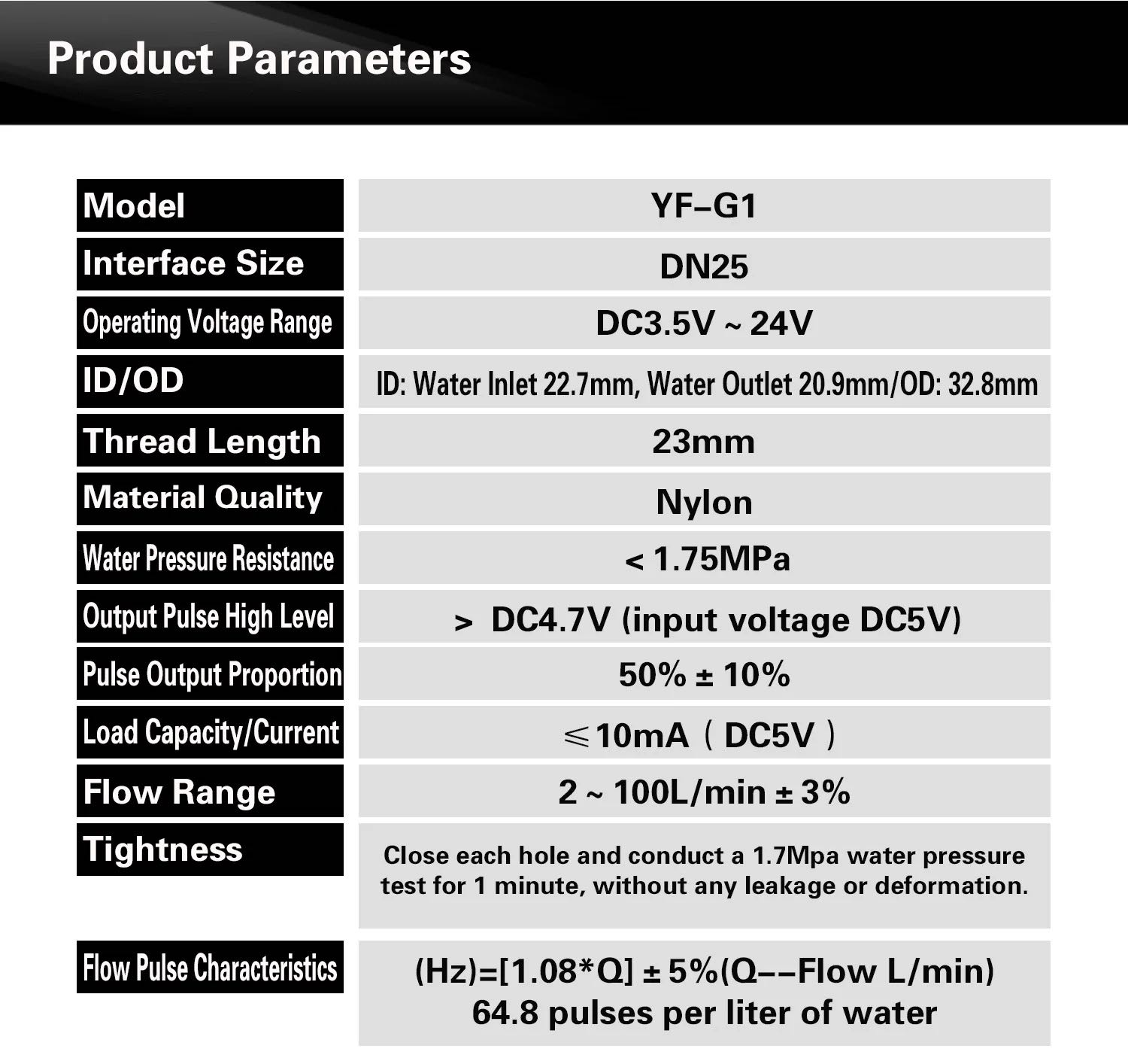
There are many projects describing the configuration of similar water flow sensors, like this one from How2Electronics). Importantly, others note that, while these sensors are often identified as requiring an operating voltage of 5V – 24V, or even the 3.5V – 24V range identified in the product data illustrated above, they can be driven directly by 3.3V processors, typically the ESP8266-based NodeMCU.
Next, I originally attempted to mate the flow sensor with a Heltec WiFi LoRa 32 dev-board but, for reasons I don't yet understand, I could not get the sensor to trigger an interrupt. Using exactly the same configuration, and essentially the same software, with the NodeMCU DevKit was fine, so I just went with that.
The current NodeMCU/Flow Meter configuration is as illustrated below.
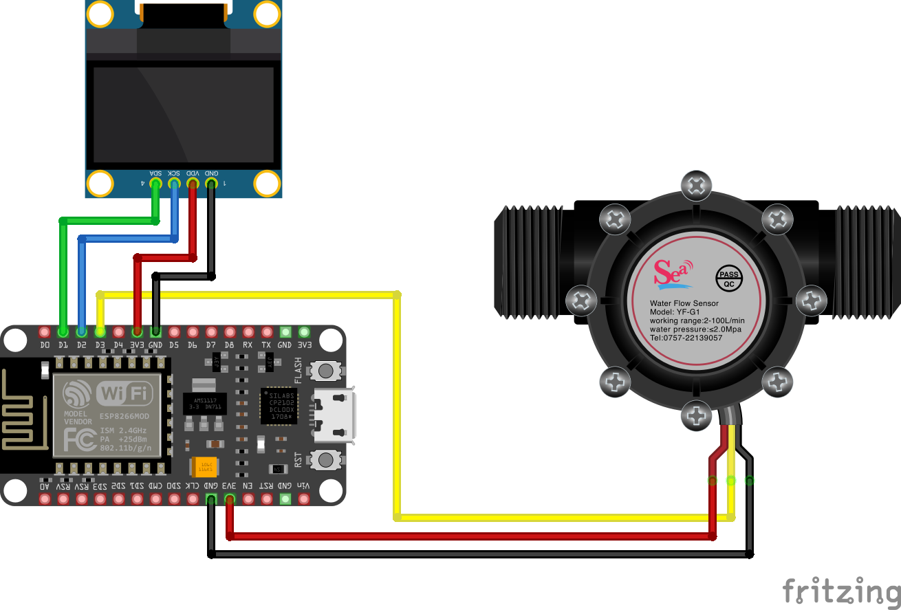
Water Flow Sensor Electrical Circuit
Pin Configuration
| NodeMCU |
OLED |
YF-G1 |
| GND |
GND |
GND |
| 3V3 |
VCC |
VCC |
| D1 (GPIO5) |
SCL |
|
| D2 (GPIO4) |
SDA |
|
| D3 (GPIO0) |
|
Sig |
|
|
|
I also encountered problems running from battery, and I still do not fully understand why. Again, everything was fine until I 'activated' the sensor—this immediately sucked the life out of the NodeMCU board! Provide power through the on-board USB connector, reset, and all was fine, which left me to question the claim that the sensor draws less than 10mA. I tried different size batteries (14500, 18500, 18650), invariably with different ratings, to no effect, and also to run the sensor at a higher voltage (5V) but, again, regardless of the size of the battery, the Node died—this is probably no surprise, since the power still comes from the battery, regardless of the voltage. This is probably not a major issue in the present case, as there will be no water flow if there is no power to run the associated pump—actually, this may not be true, there may still be leakage through the pump even when it is not actually running... This requires more investigation...
Software
While the operation of most of the examples that I have encountered is similar, one thing that does differ is the pulse frequency, which has a direct impact on the calibration of the sensor. Fortunately, one store on AliExpress includes details of the operating characteristics of several different flow sensors, specifically, and most importantly in the present context, their flow pulse characteristics.
In particular, for the present YF‑G1 sensor (see above), 64.8 pulses are generated for each litre of water that passes through. This allows us to calculate the Flow Rate as:
| Flow Rate | = | Pulse Count [pulses]
Time Interval [minutes] × 64.8 [pulses/L] | L/min |
Cut the following back to just the essentials for flow measurement.
/*
	Water Flow Sensor Test Sketch
 */

#include <Wire.h>
#include <SSD1306Wire.h>        // OLED Display

#define I2C_SCL D1 // GPIO5
#define I2C_SDA D2 // GPIO4
#define SENSOR  D3 // GPIO0

// OLED Display Settings
const int Display_I2C_Address = 0x3c;
SSD1306Wire display(Display_I2C_Address, I2C_SDA, I2C_SCL);

long currentMillis = 0;
long previousMillis = 0;
long reportStartMillis = 0;
long reportEndMillis = 0;
int timeInterval = 10000;  // In milliseconds
// float calibrationFactor = 1.08;
float pulsesPerLitre = 64.8;
volatile byte pulseCounter;
byte pulseCount = 0;
byte reportPulseCount = 0;
float flowRate;
unsigned long flowMilliLitres;
unsigned int totalMilliLitres;
float flowLitres;
float totalLitres;

// General
int reportInterval = 60;  // In seconds

void IRAM_ATTR pulseMonitor()
{
  pulseCounter++;
}

void setup()
{
  Serial.begin(115200);
  delay(500);

  Serial.println("[setup] NodeMCU Water Flow Sensor Node");
  Serial.println();

  pinMode(SENSOR, INPUT_PULLUP);

// Initialise the OLED display
  display.init();
  display.flipScreenVertically();
  display.setFont(ArialMT_Plain_10);
  display.setTextAlignment(TEXT_ALIGN_LEFT);
  display.drawString(5,5,"I2C Flow Sensor");
  display.display();

  pulseCounter = 0;
  flowRate = 0.0;
  flowMilliLitres = 0;
  totalMilliLitres = 0;
  previousMillis = 0;

  attachInterrupt(digitalPinToInterrupt(SENSOR), pulseMonitor, FALLING);

  Serial.println("[setup] Set-up Complete");
  Serial.println();
}

void loop()
{
  currentMillis = millis();
  if (currentMillis - previousMillis > timeInterval)
  {

    pulseCount = pulseCounter;
    reportPulseCount = reportPulseCount + pulseCount;

    // Because this loop may not complete in precise timeIntervals we calculate
    // the number of milliseconds that have passed since the last execution and use
    // that to scale the output. We also apply the calibrationFactor to scale the output
    // based on the number of pulses per second per units of measure (litres/minute in
    // this case) coming from the sensor.

//    flowRate = ((1000.0 / (millis() - previousMillis)) * pulse1Sec) / calibrationFactor;
//    Serial.print("[loop] pulseCount: ");
//    Serial.println(pulseCount);
//    Serial.print("[loop] pulsesPerLitre: ");
//    Serial.println(pulsesPerLitre);
    timeInterval = millis() - previousMillis;
    flowRate = pulseCount/(((float)timeInterval / 60000) * pulsesPerLitre);

//    Serial.print("[loop] flowRate: ");
//    Serial.println((float)flowRate,2);

    previousMillis = millis();
    pulseCounter = 0;

    // Divide the flow rate in litres/minute by (60/timeInterval) to determine how many litres have
    // passed through the sensor in this timeInterval, then multiply by 1000 to
    // convert to millilitres.
    flowLitres = (flowRate / (60000 / (float)timeInterval));
    flowMilliLitres = flowLitres * 1000;

    // Add the millilitres passed in this second to the cumulative total
    totalMilliLitres += flowMilliLitres;
    totalLitres += flowLitres;

    // Print the flow rate for this second in litres / minute
    Serial.print("Flow rate: ");
    Serial.print(float(flowRate));  // Print the integer part of the variable
    Serial.print(" L/min");
    Serial.print("\t");       // Print tab space

    display.clear();

    display.drawString(10,0,"Water Flow Meter");
    display.display();

    display.setFont(ArialMT_Plain_24);
    display.drawString(0,15,"R:");
    display.drawString(30,15,String(float(flowRate)));

    display.setFont(ArialMT_Plain_10);
    display.drawString(110,28,"L/M");

    // Print the cumulative total of litres flowed since starting
    Serial.print("Output Liquid Quantity: ");
    Serial.print(totalMilliLitres);
    Serial.print(" mL / ");
    Serial.print(totalLitres);
    Serial.println(" L");

    display.setFont(ArialMT_Plain_24);
    display.drawString(0,40,"V:");
    display.drawString(30,40,String(totalLitres));
    display.setFont(ArialMT_Plain_10);
    display.drawString(110,53,"L");
    display.display();

  }
}
|
See also A-3PO/~/LoRaWiFiV2FlowMeter.ino.
Further details pending

