

Watchdog Timer

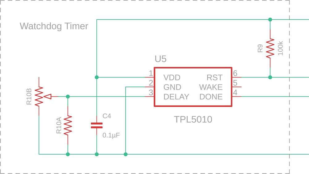
This section deals with watchdog timer circuitry, based on the Texas Instruments TPL5010 IC, that has been configured in IoT Node configurations. A watchdog timer helps a Node to recover, from a hardware or software fault that causes the processor to hang, by automatically initiating a processor reboot when the processor fails to 'pat the dog' within a preset time interval.
The watchdog timer circuit is simply a variation of the sleep timer circuit described elsewhere on this site, based on the TI TPL5010 rather than the TI TPL5111 timer IC. The original implementation of this watchdog timer circuit, illustrated above, is described elsewhere on this site.
MOSFET Switch Addition
While the basic circuit illustrated above worked as intended when boards were running on battery, it appeared to be inactive when a board was powered by a 5V source, either through its USB port or through an external supply via the 5V pin. It turned out that, while the TPL5010 was operating as expected in one sense and pulling its RST pin down when the timer expired, it was unable to pull the RST pin on several host Heltec boards low enough to trigger a reset when the board was being powered by a 5V source. From the information that I have on the power supply circuitry on either the CubeCell, WiFi LoRa 32 or Wireless Stick Lite boards, I cannot see why this would be the case, so there is clearly something going on that I simply do not understand.
Whatever the cause, the basic circuit would not trigger a reset in applications where I was powering a Node through an external supply, specifically in my Gateway Nodes, based on the WiFi LoRa 32 board, and the Power Switch Node, based on the CubeCell board.
To address this problem, a MOSFET switching arrangement was added to the circuit. The MOSFETs were switched as expected by the TPL5010, regardless of the operating voltage, and when triggered connected the host RST pin directly to ground, initiating the intended reset.
The theory of operation of the MOSFET arrangement is similar to that described in the section on battery management although the logic in the present case is inverted—by reversing the roles of the two MOSFETs, the circuit is switched on by LOW rather than HIGH logic.
Watchdog Timer Daughter Board
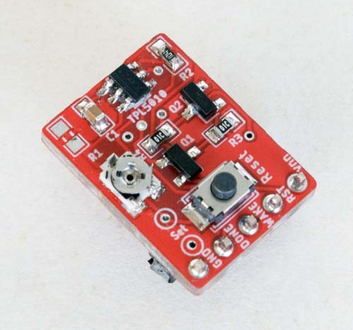
A complete watchdog timer circuit, including an optional timer reset button and the MOSFET switching extension, has also been implemented on a stand-alone daughter board, the schematic for which is presented below.
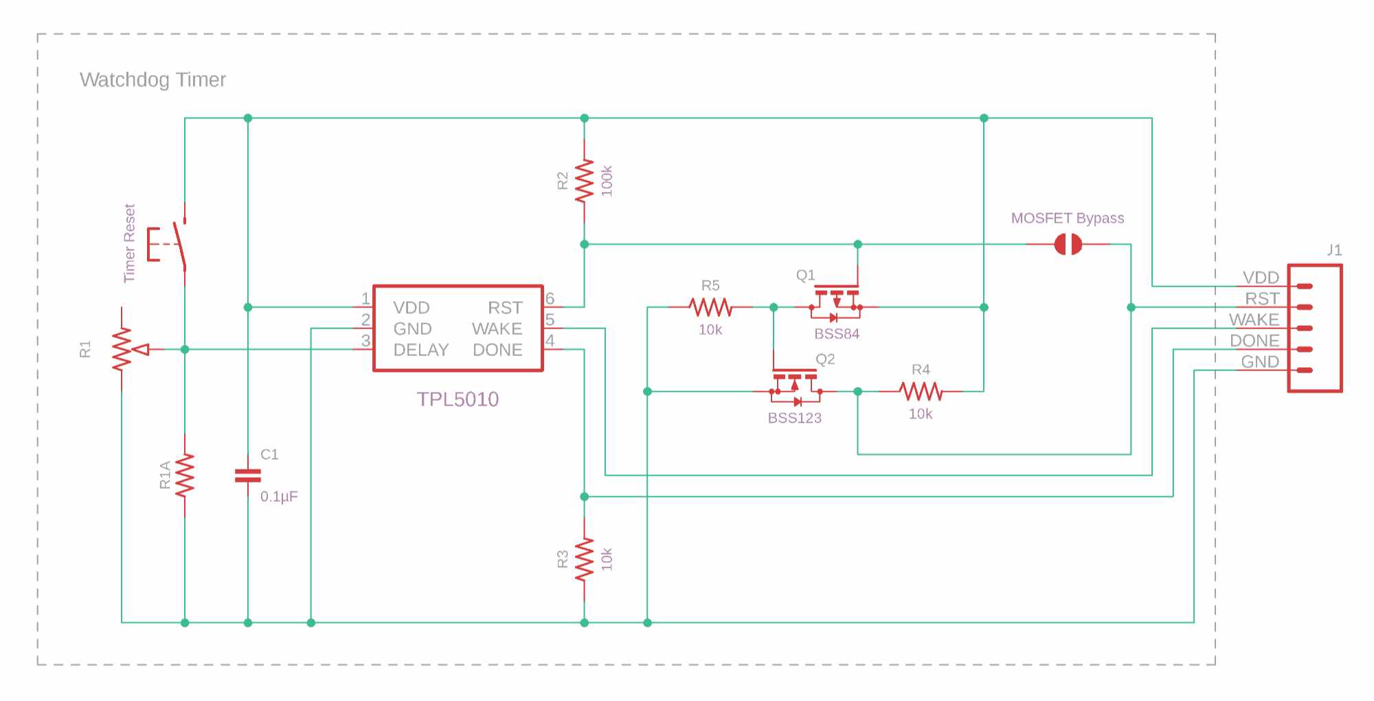
TPL5010 Watchdog Timer with MOSFET Switching
Part of the motivation for developing the daughter board was that the watchdog timer as originally implemented had never really worked as expected and I wanted a platform that I could use to further investigate its behaviour. Apart from the failure to reset some processors when they were running from a 5V power source, there was a significant discrepancy between the timeout period observed for a given DELAY pin resistance and that quoted in the datasheet.
I ultimately discovered a description of this very problem on one of the TI forums, with the recommendation to include a shunt resistor on the DONE pin, presumably so that the pin was not left floating on start-up, when the DELAY resistance is measured and the timeout set. To this end, a 10kΩ pull-down resistor has been configured on the DONE pin (refer to the daughter board PCB page for additional detail).
The full implementation also breaks out the WAKE pin, which I have not generally needed to use in my applications. The daughter board can be configured without the MOSFETs and their associated resistors, if they are not required, by simply bridging a solder jumper on the board (see here for PCB CAD and CAM files).
Following the broad philosophy adopted in many applications presented on this site, this provided an additional degree of flexibility in the way in which a watchdog timer could be included in a Node configuration.