A4a LoRa ESP32-WROOM-32 PCB
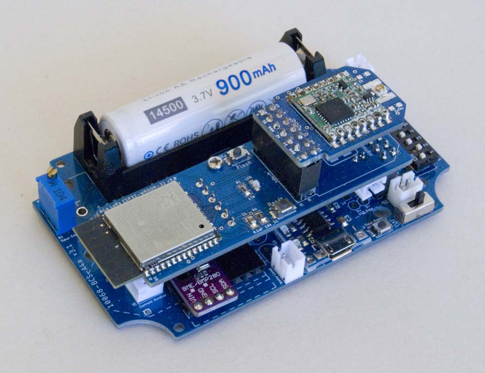
This board is designed to support the Espressif ESP32-WROOM-32 processor module.
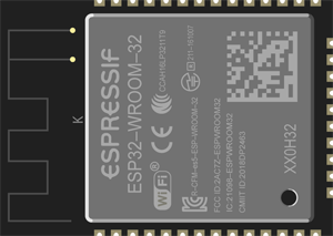
Espressif ESP32-WROOM-32 Processor
Board Layout
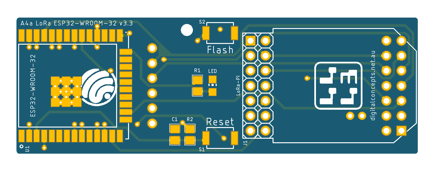
The various elements are identified in the board schematic and laid out as illustrated below:
| Top | Bottom |
|---|---|
 |
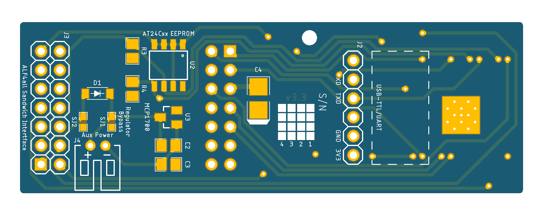 |
A4a LoRa ESP32-WROOM-32 [v3.3] PCB
See here for CAD and CAM files.
Configuration
Basic Configuration
With the obvious exception of the processor itself, most of the components on this board are optional. Those elements that need to be included for basic operation are:
- ESP32 processor
- ESP32 serial interface header
- A4a 'Sandwich' interface header
- Reset button
- Flash button
Processor
- Espressif ESP32-WROOM-32 Processor
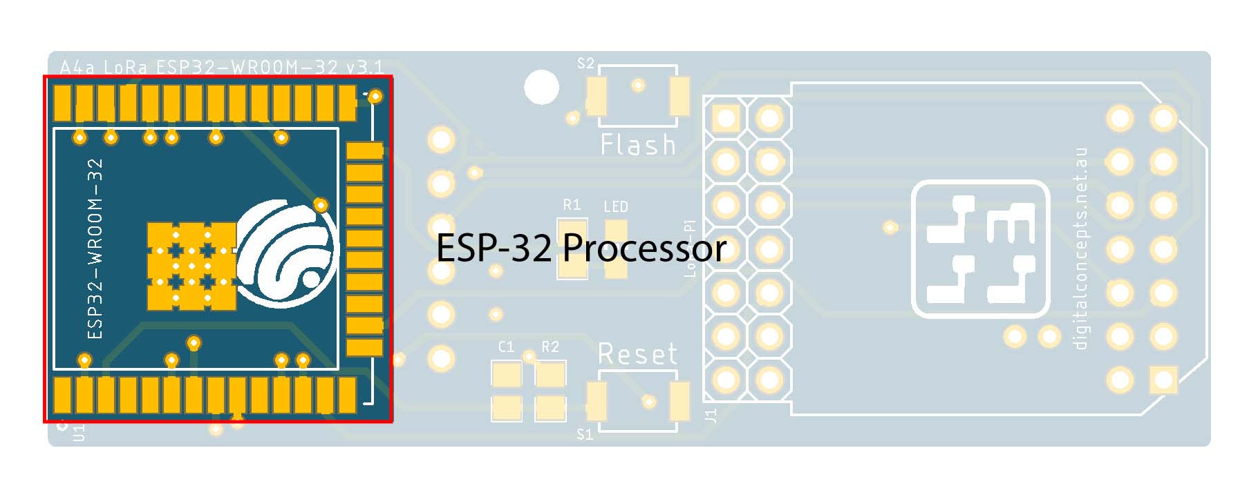 |
ESP32 Processor
Serial Interface
- 6 Pin Right Angle Female Header (J2)
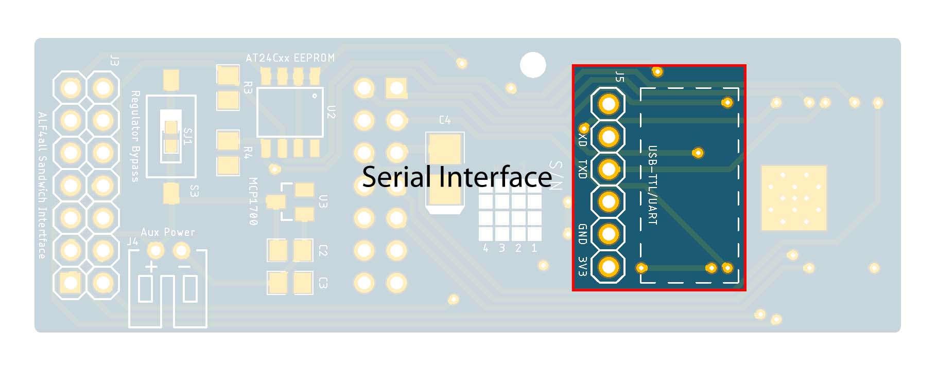 |
ESP32 Serial Interface
The Programmer Interface on the A4a LoRa ESP32 board is a 1×6 right-angle female header, located on the 'back' of the board, that mates with the male header on the serial interface module.
[Male] FTDI USB-UART Configuration
Note that there are several different serial interface modules available on the market. Some, like ones used on the Arduino Pro Mini, use a 6-pin header, which may or may not have the same pin configuration as that illustrated above, while others, typically ESP8266 processor modules, the ESP-01 programmer 2×4 pin header.
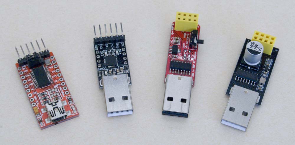
Serial Adaptors
I started out assuming that I'd use an ESP-01 programmer for both of my ESP processors, but I could not get either of the ESP-01 programmers to work reliably with the ESP32 processor and abandoned that option early on in favour of the present one. Noting possible variations in the pin configurations, I used two different 6-pin interface modules without any problem but arbitrarily settled on the present configuration (the black module, second from the left in the above photo, which uses the Silicon Labs UART).
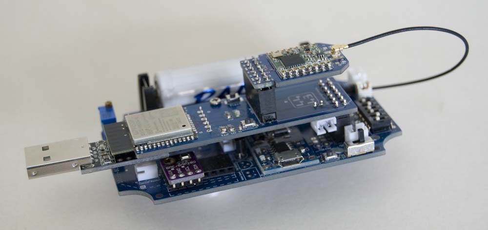
A4a LoRa ESP32 FTDI Serial Adaptor
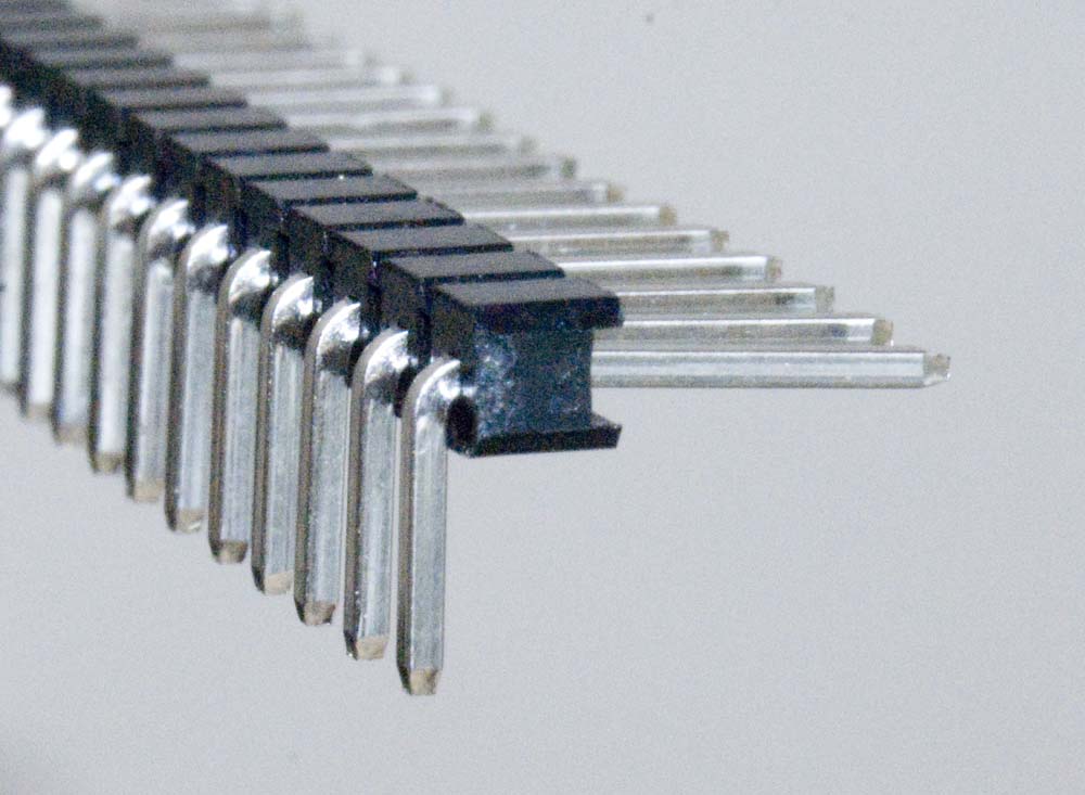
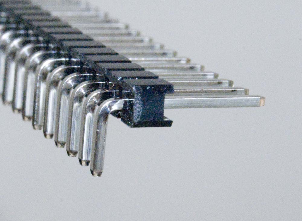
I also replaced the original right angle header on the module with the 'low profile' version that I use on most of my boards. This allows the serial adaptor to be used while the processor board is in place on a fully configured base board as illustrated above.
| This is the one I generally use | ||
|---|---|---|
 |
 |
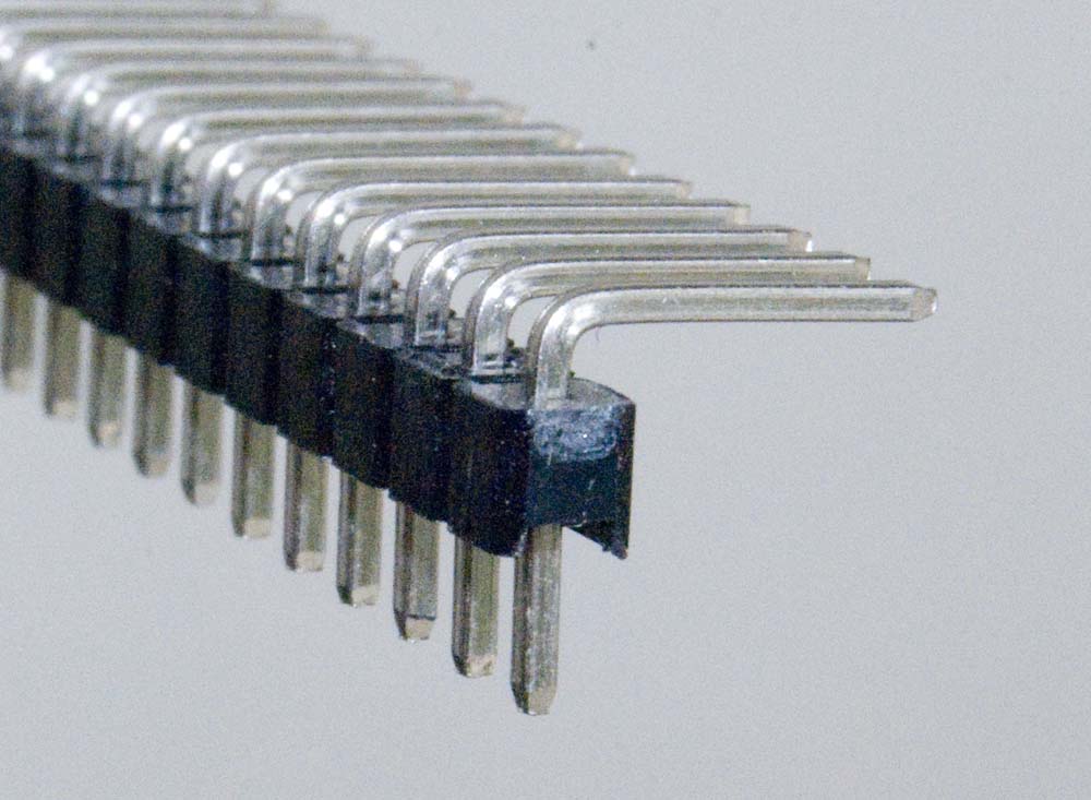 |
Male Right Angle Header Configurations
ALF4all Sandwich Interface Header
- 2×7 Pin Straight Male Header (J3)
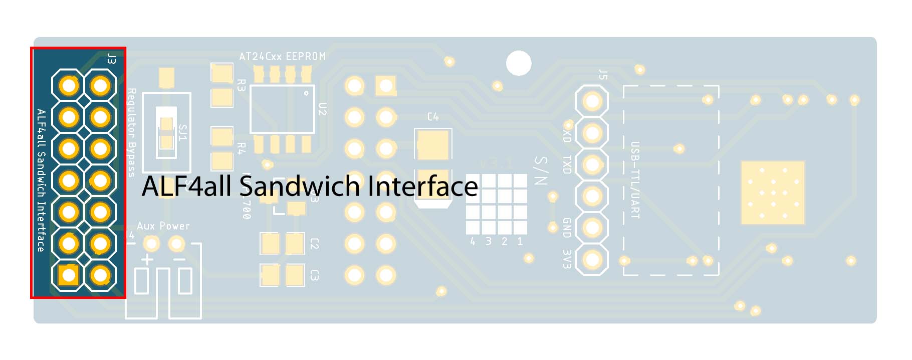 |
ALF4all Sandwich Interface [Male]
All of the A4a processor modules are designed to plug into one of the A4a base boards (e.g. 10068-BCS-A4a). When configured with one of these power supply/base boards, the processor draws its power from and connects to relevant sensors through the base board. (These processor modules can, nonetheless, operate independently if they are powered through the auxiliary power connector.)
Rather than confuse matters by presenting different versions of the A4a Sandwich interface pin configuration, note that the male header on the present module is the mirror image of the mating female header on the A4a base boards (e.g. 10068-BCS-A4a), the configuration of which is illustrated below.
ALF4all Sandwich Interface [Base Board – Female Header] Configuration
When using the A4a Sandwich Interface to supply power, solder jumper SJ2 must also be bridged unless the auxiliary power connector and associated Schottky diode are also being configured.
Reset Button
- 2P Momentary Switch (S1)
- 10kΩ 0805 Resistor (R2)
- 0.1µF 0805 Capacitor (C1)
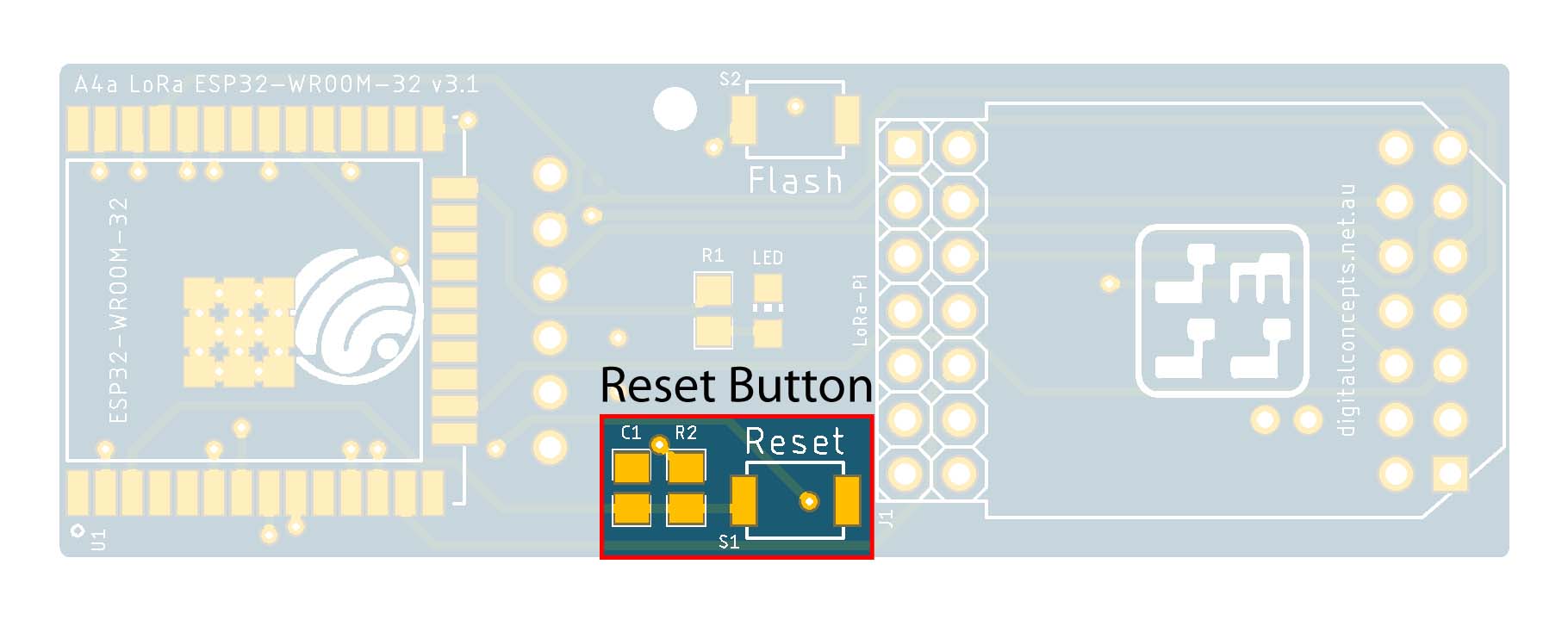 |
Reset Button
Pressing the Reset Button on its own initiates a processor reboot. If pressed while the Flash Button is also pressed, the processor enters programming mode. Otherwise, the EN pin must be held High (R2).
The capacitor is configured to dampen voltage spikes that may occur when the Reset Button is pressed.
Flash/Program Button
- 2P Momentary Switch (S2)
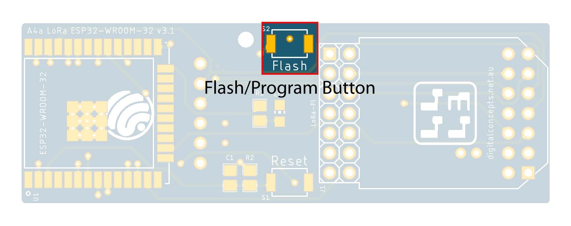 |
Flash/Program Button
The Flash button is used to facilitate programming of the ESP-12 processor. To enter programming mode, hold down the Flash button and press the Reset button. Both buttons can then be released and code can be downloaded to the processor through the serial interface.
Pull-up/Pull-down Resistors
As with the ESP-12 processors, several pins on the ESP32 processor must be in a specific state during the boot cycle. In the present case, bhowever, no special hardware configuration is required on our part.
This article from Random Nerd Tutorials provides an excellent overview of ESP32 pins and functions.
EEPROM
- AT24Cxx (02–64KB) SOP-8 EEPROM (U2)
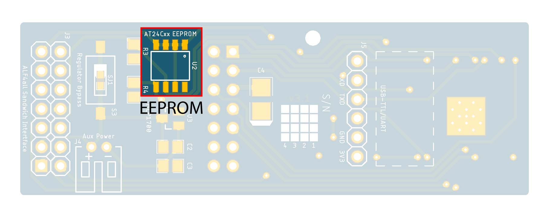 |
EEPROM
Pull-up resistors are generally required on the [SCL/SDA] control lines for the I2C interface used to access the EEPROM.
Pull-up Resistors
- 10kΩ 0805 Resistor (R3)
- 10kΩ 0805 Resistor (R4)
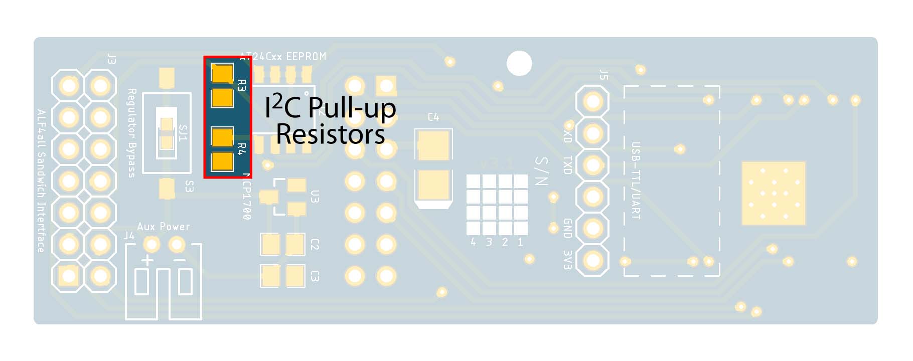 |
I2C Pull-up Resistors
Auxiliary Power Connector
- 2P PH2.0 Right Angle JST Connector (J4)
- 1N5819 SOD-123 Schottky Diode (D1)
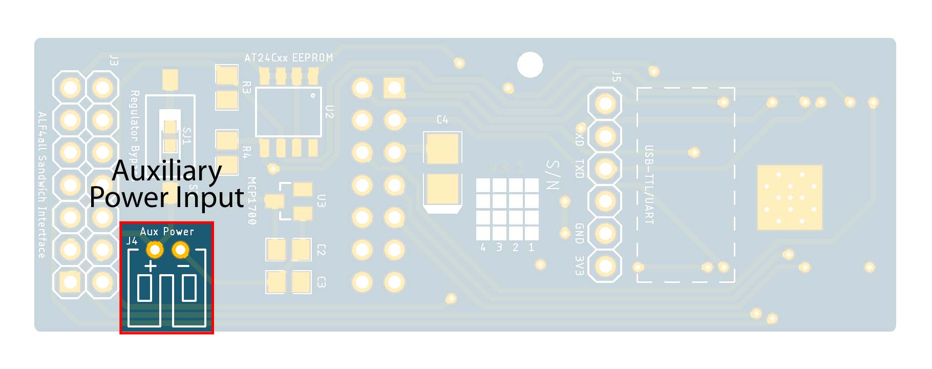 |
Auxiliary Power Connector
- 2P PH2.0 Right Angle JST Connector
Use of the auxiliary power PH2.0 connector, for something like a LiPo battery, requires the configuration of the voltage regulator to keep the supply voltage acceptably close to 3.3V.
If the A4a Sandwich Interface is configured, and it usually will be, the Zener diode (D1) should also be configured and the solder jumper SJ2 left open, to protect any power source connected through this interface.
Voltage Regulator
- MCP1700T-3302E SOT-23-3 3.3V Voltage Regulator (U3)
- 1µF 0805 Capacitor (C2)
- 1µF 0805 Capacitor (C3)
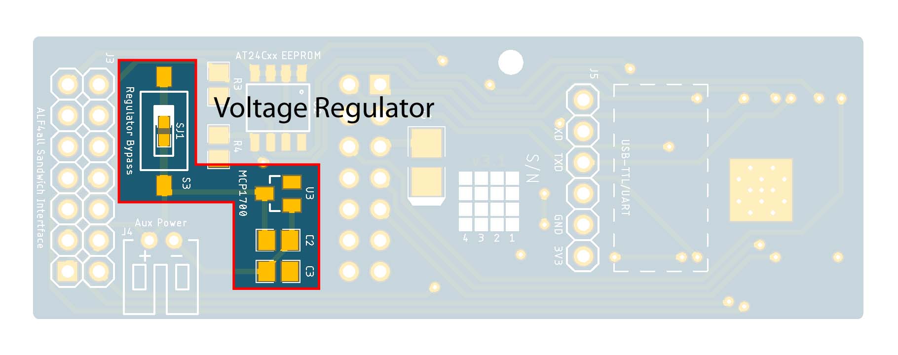 |
Voltage Regulator
In the present environment, where power will usually be supplied through one of the BCS-A4a base boards, this voltage regulator is not required. It is really only needed when power supplied though the Auxiliary Power Connector needs to be regulated, for example when using a LiPo battery, which has the potential to provide more than the 3.6V maximum rated voltage for the ESP32 module.
If the external power source is something like a LiFePO4 battery (2.5V–3.65V), and the regulator is not configured, the regulator bypass solder jumper (SJ1) must be bridged.
LoRa-Pi Header
- 2×7 Pin Straight Male Header (J1)
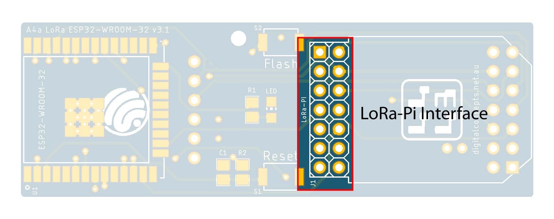 |
LoRa-Pi Header
For my prototyping work, I have used my LoRa-Pi Hat to interface with the RFM95W radio that is used with processors—Espressif or Arduino (Atmel)—that do not include an onboard radio. The simple reason is that this allowed me to create many configuration variations without having to use a new radio module for every one. The configuration of the RFM95W interface is simply that which allows direct connection to a Raspberry Pi [male] header—the LoRa-Pi Hat, itself, thus has a female header—using the Hallard pin configuration. The LoRa-Pi interface header on the A4a processor boards is thus also a male header, configured as illustrated below.
LoRa-Pi Interface [Male] Configuration
Power Conditioning Capacitor
- 220µF 3528-21 Tantalum Capacitor (C4)
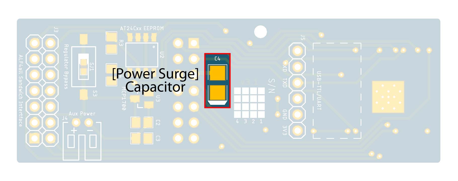 |
Power Conditioning Capacitor
At one point, I encountered a problem with the RFM95W/ESP-12 configuration when coming out of deep sleep. It was never entirely clear what the problem was, but one of the suggestions I found was that it might be the result of power supply instability. Whether or not this was ever going to be a problem with the ESP32 processor, this configuration option is also included here to cover off that possibility.


![[6 pin] USB-UART/Serial Interface](../arduino/content/images/iot/assembly/A4a/[6 pin] USB-Serial Interface.jpg)

