SD Card Reader
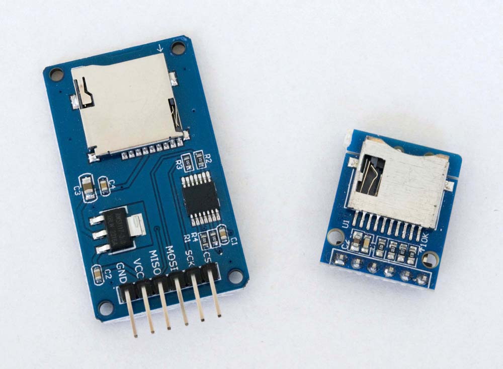
This section provides details of the configuration of an SD card reader on the SPI bus of several different processors that I have used in IoT Node configurations.
I have tested the two SD card readers illustrated above in my IoT node configurations. The card reader itself in both is a 3.3V device and the module on the right in the photo above is driven by a 3.3V supply. The module on the left is designed to be driven by a 5V supply and thus includes both a 3.3V regulator and a logic level shifter to allow it to be interfaced with a 5V processor. Given that all of my projects are based on 3.3V processors, I do not really have a need for the 5V module—I bought the two originally because I was unsure whether or not there was more to the 5V module than just the regulator and logic level shifter and, in the event, there does not appear to be. The 5V module uses a spring loaded card holder, which I find a little nicer to use than the more basic item used on the 3.3V module, but the compact size of the smaller module makes it the more attractive option in my situation, regardless of voltage considerations. Apart from that, and the physical order of the interface pins on the two cards, the two are effectively identical.
At one level, connecting up an SD card reader is a pretty straightforward exercise. The devil here, however, is in the detail. Even though the example sketches included with the SD library are relatively straightforward in themselves, different processors invariably require specific implementations of the SPI library software and use different, and sometimes quite specific, pins for their SPI bus(es). One can lose a lot of hair getting things to work if these two issues are not addressed at the outset.
Arduino Pro Mini
Hardware Configuration
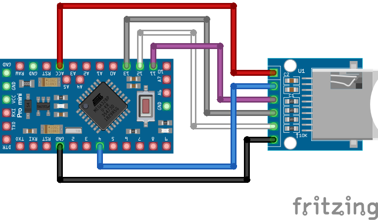
The hardware configuration used in the present example for the microSD card reader with a 3.3V Arduino Pro Mini is illustrated below.
Arduino Pro Mini-microSD Card Reader Electrical Circuit
Pin Configuration
| Arduino Pro Mini | microSD Card Reader (SPI) |
|---|---|
| 3V3 | 3V3 |
| 4 | CS |
| 12 | MISO |
| 11 | MOSI |
| 13 | CLK |
| GND | GND |
Software Considerations
I'm yet to actually test the microSD card reader with the Pro Mini.
Details pending
NodeMCU (ESP8266)
Hardware Configuration
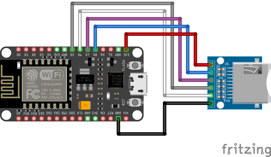
The hardware configuration used in the present example for the microSD card reader with a NodeMCU [ESP8266] Dev-Board is as illustrated below.
NodeMCU-microSD Card Reader Electrical Circuit
Pin Configuration
| NodeMCU | microSD Card Reader (SPI) |
|---|---|
| 3V3 | 3V3 |
| D8 (GPIO15) | CS |
| D7 (GPIO13) | MOSI |
| D5 (GPIO14) | CLK |
| D6 (GPIO12) | MISO |
| GND | GND |
Software Considerations
There were no special considerations required when configuring the SD card reader with the NodeMCU Dev-Board. With the above configuration (see also configuration details for Espressif processors in the ESP32 section below), the examples provided with the standard Arduino/Sparkfun SD library execute successfully without modification.
ESP32
While it would appear to have little relevance with reference to the way Heltec has chosen to configure its ESP32-based boards, the following extract from the SD.cpp library file is included here for information purposes.
/*
 * pin 1 - not used          |  Micro SD card     |
 * pin 2 - CS (SS)           |                   /
 * pin 3 - DI (MOSI)         |                  |__
 * pin 4 - VDD (3.3V)        |                    |
 * pin 5 - SCK (SCLK)        | 8 7 6 5 4 3 2 1   /
 * pin 6 - VSS (GND)         | ▄ ▄ ▄ ▄ ▄ ▄ ▄ ▄  /
 * pin 7 - DO (MISO)         | ▀ ▀ █ ▀ █ ▀ ▀ ▀ |
 * pin 8 - not used          |_________________|
 *                             ║ ║ ║ ║ ║ ║ ║ ║
 *                     ╔═══════╝ ║ ║ ║ ║ ║ ║ ╚═════════╗
 *                     ║         ║ ║ ║ ║ ║ ╚══════╗    ║
 *                     ║   ╔═════╝ ║ ║ ║ ╚═════╗  ║    ║
 * Connections for     ║   ║   ╔═══╩═║═║═══╗   ║  ║    ║
 * full-sized          ║   ║   ║   ╔═╝ ║   ║   ║  ║    ║
 * SD card             ║   ║   ║   ║   ║   ║   ║  ║    ║
 * Pin name         |  -  DO  VSS SCK VDD VSS DI CS    -  |
 * SD pin number    |  8   7   6   5   4   3   2   1   9 /
 *                  |                                  █/
 *                  |__▍___▊___█___█___█___█___█___█___/
 *
 * Note:  The SPI pins can be manually configured by using `SPI.begin(sck, miso, mosi, cs).`
 *        Alternatively, you can change the CS pin and use the other default settings by using `SD.begin(cs)`.
 *
 * +--------------+---------+-------+----------+----------+----------+----------+----------+
 * | SPI Pin Name | ESP8266 | ESP32 | ESP32‑S2 | ESP32‑S3 | ESP32‑C3 | ESP32‑C6 | ESP32‑H2 |
 * +==============+=========+=======+==========+==========+==========+==========+==========+
 * | CS (SS)      | GPIO15  | GPIO5 | GPIO34   | GPIO10   | GPIO7    | GPIO18   | GPIO0    |
 * +--------------+---------+-------+----------+----------+----------+----------+----------+
 * | DI (MOSI)    | GPIO13  | GPIO23| GPIO35   | GPIO11   | GPIO6    | GPIO19   | GPIO25   |
 * +--------------+---------+-------+----------+----------+----------+----------+----------+
 * | DO (MISO)    | GPIO12  | GPIO19| GPIO37   | GPIO13   | GPIO5    | GPIO20   | GPIO11   |
 * +--------------+---------+-------+----------+----------+----------+----------+----------+
 * | SCK (SCLK)   | GPIO14  | GPIO18| GPIO36   | GPIO12   | GPIO4    | GPIO21   | GPIO10   |
 * +--------------+---------+-------+----------+----------+----------+----------+----------+
 *
 * For more info see file README.md in this library or on URL:
 * https://github.com/espressif/arduino-esp32/tree/master/libraries/SD
 */
Note: When using any of the Heltec V3 boards, ensure that the most recent version of the Heltec ESP32 Dev-Boards support software has been installed (Arduino IDE Library Manager)—at the time of writing, this is v2.1.2—which also requires installation of the Espressif esp32 board files (Arduino IDE Board Manager). Some libraries and examples in earlier versions do not allow for the fact that SPI peripherals must be configured on the second SPI bus when using the V3 boards.
Hardware Configuration
Heltec WiFi LoRa 32 (V2)
The ESP32 MCU and associated support libraries provide support for two SPI buses. The SX1276 LoRa Node chip on the WiFi LoRa 32 boards is configured on the first SPI bus, SPI0 (usually referenced simply as SPI). On the pre-V3 WiFi LoRa 32 boards, other devices can be configured either on this SPI bus, using a CS pin other than that used for the LoRa Node chip (GPIO18), or on the second SPI bus, SPI1, which must then be configured appropriately.
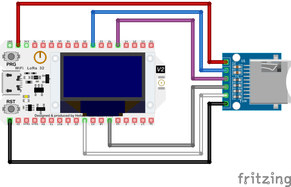
The hardware configuration used to configure the microSD card reader on the primary SPI bus of the Heltec WiFi LoRa V2 platform is as illustrated below.
WiFi LoRa 32 (V2)-microSD Card Reader Electrical Circuit
Pin Configuration
| WiFi LoRa 32 [V2] | microSD Card Reader (SPI) |
|---|---|
| 3V3 | 3V3 |
| GPIO33 | CS |
| MOSI (GPIO27) | MOSI |
| SCK (GPIO5) | CLK |
| MISO (GPIO19) | MISO |
| GND | GND |
Heltec WiFi LoRa 32 (V3)
The SX1262 LoRa node chip on the WiFI LoRa 32 V3 board is configured on the first SPI bus, SPI0, the pins for which are not broken out and are thus inaccessible for any other purpose. As a consequence, any peripheral device that needs to use an SPI bus must be configured on the the second SPI bus, SPI1.
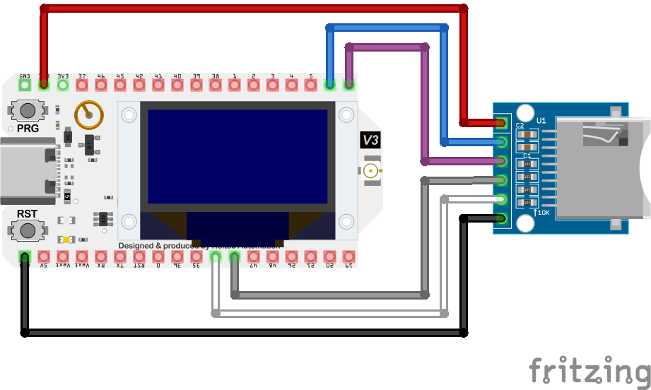
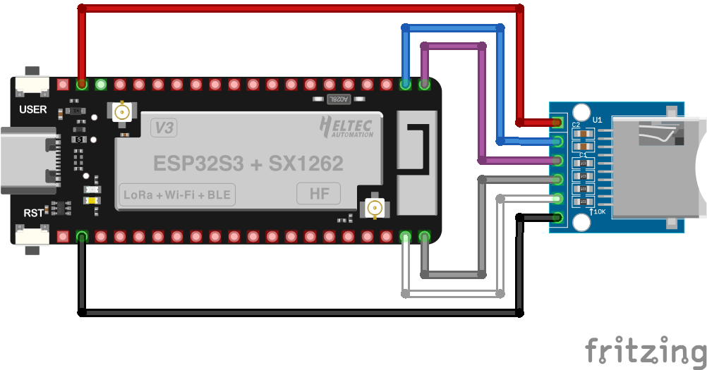
The hardware configuration used in the present example to connect the microSD card reader with the Heltec WiFi LoRa V3 platform is as illustrated below.
WiFi LoRa 32 (V3)-microSD Card Reader Electrical Circuit
Pin Configuration
| WiFi LoRa 32 [V3] | microSD Card Reader (SPI) |
|---|---|
| 3V3 | 3V3 |
| GPIO6 | CS |
| GPIO7 | MOSI |
| GPIO33 | CLK |
| GPIO34 | MISO |
| GND | GND |
Note that, while certain default pins are usually defined for the primary SPI bus, any pins supporting digital I/O and that are not reserved for some other function can generally be used for the second SPI bus.
Heltec Wireless Stick Lite (V3)
On the Wireless Stick Lite V3 board, the SX1262 LoRa node chip is once again configured on primary SPI bus, the pins for which are not broken out and hence not accessible. Again, as a consequence, any peripheral device that needs to use an SPI bus must be configured on the the second SPI bus, SPI1.
The hardware configuration of the microSD card reader and Heltec Wireless Stick Lite V3 platform used in the present example is as illustrated below.
Wireless Stick Lite (V3)-microSD Card Reader Electrical Circuit
Pin Configuration
| Wireless Stick Lite [V3] | microSD Card Reader (SPI) |
|---|---|
| 3V3 | 3V3 |
| GPIO2 | CS |
| GPIO3 | MOSI |
| GPIO4 | CLK |
| GPIO5 | MISO |
| GND | GND |
I have used various pin configurations throughout testing and they all work equally well. The main consideration is probably that the relevant pins support both input and output and, of course, that individual devices on the same SPI bus use different CS pins.
Software Considerations
To use the second SPI bus as in the configuration of the V3 boards above, we need to include the relevant details in any sketch:
|
// WiFi LoRa 32 V3 SPI1 pin definitions #define SCK1 GPIO30 #define MISO1GPIO29 #define MOSI1GPIO7 #define CS1 GPIO6 // Wireless Stick Lite V3 SPI1 pin definitions #define SCK1 GPIO4 #define MISO1GPIO5 #define MOSI1GPIO3 #define CS1 GPIO2 SPIClass SPI1; void setup(){ . . SPIClass(1); SPI1.begin(SCK1, MISO1, MOSI1, CS1); if (!SD.begin(CS1, SPI1)) { Serial.println("Card Mount Failed"); return; } . . } |
Further details pending
Heltec CubeCell-Board [Plus]
Hardware Configuration
CubeCell-Board
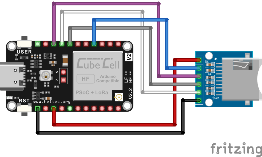
The hardware configuration of the microSD card reader with the CubeCell Dev-Board platform is as illustrated below.
CubeCell-microSD Card Reader Electrical Circuit
Pin Configuration
| CubeCell [V2] | microSD Card Reader (SPI) |
|---|---|
| 3V3 | 3V3 |
| GPIO3 | CS |
| MO | MOSI |
| SCK | CLK |
| MI | MISO |
| GND | GND |
CubeCell-Board Plus
The pins for the first SPI bus on the CubeCell Plus module are not broken out in a convient fashion. There are solder points for pins, but they are on the end of board rather than down the sides where header pins are normally connected. As with the WiFi LoRa 32 boards, the integrated LoRa node chip is configured on this primary SPI bus and it would seem that Heltec is discouraging its use for anything else.
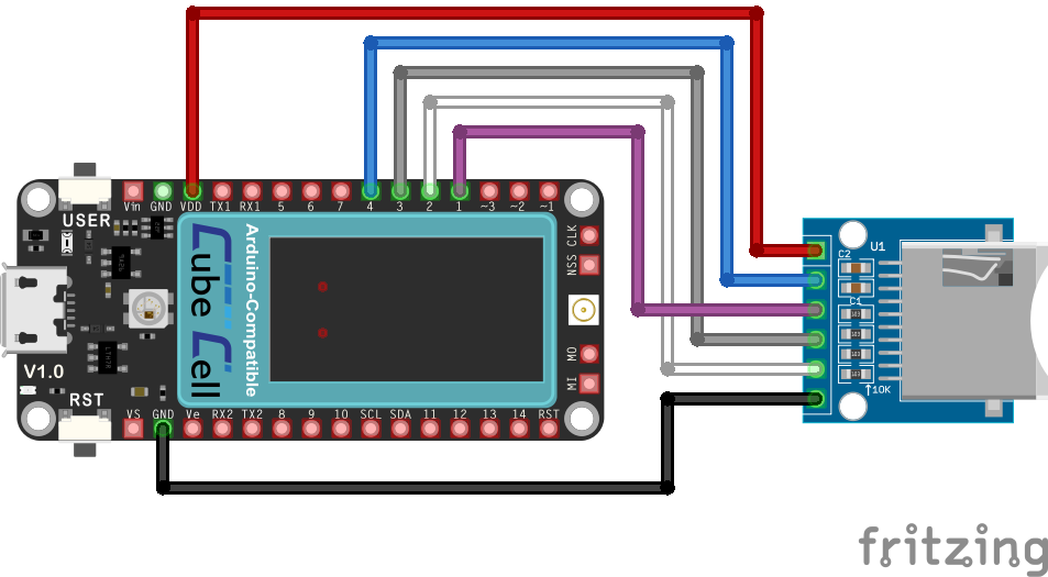
The CubeCell Plus Dev-Board does, however, support a second SPI bus, pins for which are explicitly defined in the associated pins_arduino.h file, conveniently labelled and broken out to one of the headers on the side of the board. Accordingly, as much as for an exercise in using this second bus as for the convenience of being able to simply use conveniently configured pins, the present example uses this second SPI bus on the CubeCell Plus dev-board as illustrated below.
CubeCell Plus-microSD Card Reader Electrical Circuit
Pin Configuration
| CubeCell Plus | microSD Card Reader (SPI) |
|---|---|
| 3V3 | 3V3 |
| GPIO4 | CS |
| MOSI1 (GPIO1) | MOSI |
| SCK1 (GPIO3) | CLK |
| MISO1 (GPIO2) | MISO |
| GND | GND |
Software Considerations
CubeCell SPI Library
It was a bit of a challenge getting the CubeCells to play nicely with an SD card reader. Most operations seemed to work OK with the required CubeCell support software—reading the file directory, creating files and reading file contents all seem to execute reliably—but, critically, writing to the SD card failed far more often than not.
The CubeCell environment uses the standard Arduino/Sparkfun SD library but has its own custom implementation of the SPI library, included with the CubeCell platform support software. After a lot of poking around in these two libraries, the issue turned out to simply be the delay required in the 'timeout' loop(s) in the SPIClass::transfer function in the CubeCell SPI library. This problem was ultimately resolved by increasing the value of spi_TIMEOUT used within this library.
Note that, in particular, spi_TIMEOUT is used to specify the time taken inside the receive buffer check loops within the SPI::transfer function—the setting, however, specifies the number of cycles through a loop, not a specific time. The original setting (500) may have been fine for the ASR6501 processor used in the original CubeCell dev-board, although I've never tested one to see whether or not even it would work with the current settings, but it is certainly not long enough for the [faster?] ASR6502-based CubeCell Plus and CubeCell V2 boards.
Empirical testing would suggest that the value of spi_TIMEOUT needs to be increased to at least 3500 for the ASR6502-based dev-boards and I currently use a value of 4000 to provide a little headroom. I have submitted a pull request (#293) to the Heltec GitHub repository but until that is resolved, line 26 in the CubeCell support library file SPI.cpp (~/Documents/Arduino/hardware/CubeCell/CubeCell/cores/asr650x/SPI/SPI.cpp) needs to be changed from:
| #define spi_TIMEOUT500 |
to
| #define spi_TIMEOUT4000 |
Update: 20 Dec 2024 This change has now been included in the CubeCell support software currently available on GitHub.
In my current operational environment, this change does not appear to have any negative impact on LoRa functionality and both the SX1262 LoRa Node chip and the SD card reader coexist happily on the same SPI bus, noting of course that each must use a discrete pin for their respective CS connections.
Using SPI1 on the CubeCell-Board Plus
To use the second SPI bus, SPI1, on the CuebCell-Board Plus platform, relevant sketches also need to include appropriate definitions for that SPI bus, e.g.
|
// SCK1, MISO1 & MOSI1 are defined in pins_arduino.h #define CS1GPIO4 void setup(){ . . SPI1.begin(SCK1, MISO1, MOSI1, CS1); if (!SD.begin(CS1)) { Serial.println("Card Mount Failed"); return; } . . } |
Notably, at the time of writing, there was no SD initialisation method in the standard Arduino/Sparkfun SD library, which is currently the library that is used with the CubeCells, equivalent to that provided within the ESP32 SD library that enables the specification of the SPI bus to be used—it is, by default, the first SPI bus, SPI. Fortunately, the library does include a mechanism to define the SPI bus to be used, although the relevant definition is buried deeply within the support software for boards that require the use of anything other than the first SPI bus—this definition also applies at the library level and cannot be modified within individual sketches. To use the second SPI bus on the CubeCell-Board Plus then, an appropriate definition needs to be included in the CubeCell-Board Plus pins_arduino.h file.
I have submitted a pull request (#294) to the Heltec GitHub repository to make this change, since it will usually be the second SPI bus that is used to connect to external SPI devices, but until that is resolved, the following definition also needs to be added to the CubeCell-Board Plus pins_arduino.h file (~/Documents/Arduino/hardware/CubeCell/CubeCell/variants/CubeCell-BoardPlus/pins_arduino.h) to use the SPI1 bus for the microSD card reader:
| #define SDCARD_SPISPI1 |
Update: 17 Jan 2025 This change has now been included in the CubeCell support software currently available on GitHub. There should also now be a sketch included in the library example sketches (pull request #295) that uses the second SPI bus on the CubeCell Dev-Board Plus.
Further details pending


