

Battery Charge Management
This section deals with battery charge management and the configuration of power-source-control circuitry that is incorporated into several IoT Node configurations. Recognising the problems associated with using the TP4056 module to charge a battery under load, the MOSFET circuit illustrated below isolates the battery when it is being charged, that being when the circuit is connected to an external power source, then automatically switches it back into the circuit to provide power when the external power source is removed.
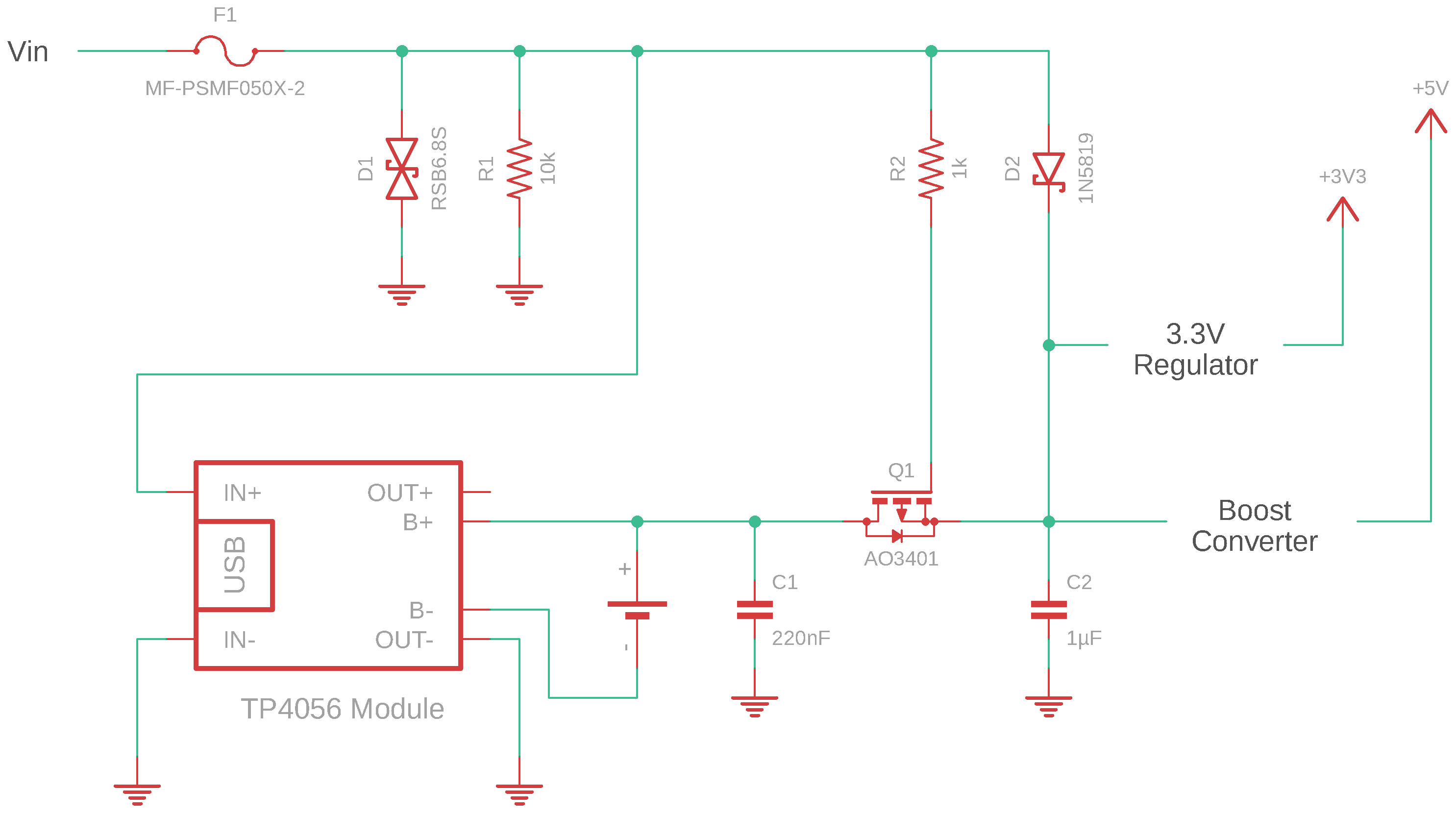
Power Source Switching Circuit
Details pending
In the mean time, refer to the descriptions of battery voltage measurement and power source switching circuitry provided elsewhere on this site.
Battery Charge Management Daughter Board
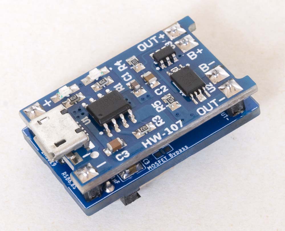
I have recently developed a daughter board that includes the various battery charge management elements—the TP4056 charging module, the battery voltage measurement circuitry described elsewhere on this site, and the power source switching circuitry described above. The commercially available TP4056 module is mounted above the PCB containing the other circuitry, minimising the overall footprint of the daughter board.
The configuration of the three circuit elements is illustrated in the following schematic.
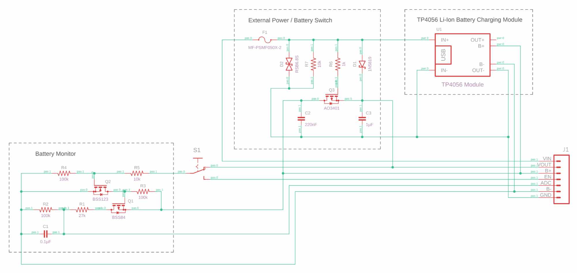
Battery Charge Management Circuit
Given the number of components that have been consumed in my various prototyping exercises, I should really have done this from the outset. This now allows me to simply reuse these elements when developing new board configurations.
Note that this daughter board serves no purpose when using the more recent versions of the Heltec boards discussed on this website as they all include this functionality.
The relevant CAD and CAM files can be downloaded from the DB-BCM4056 PCB page.