A4a LoRa NodeMCU PCB
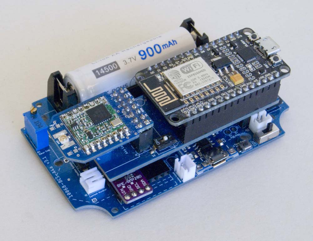
This board is designed to support the Amica NodeMCU V2 development board.
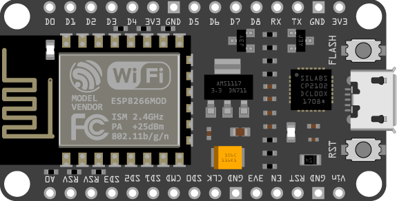
Amica [ESP-12E] NodeMCU Module
This board was really only created to help simplify the development of the 'native' ESP-12 processor board. Having used the NodeMCU Dev Board in previous applications, it made it much easier to troubleshoot basic problems with my early ESP-12 board configurations. As a consequence, NodeMCU configurations are, quite intentionally, functionally identical to the comparable A4a LoRa ESP-12 configurations.
Board Layout
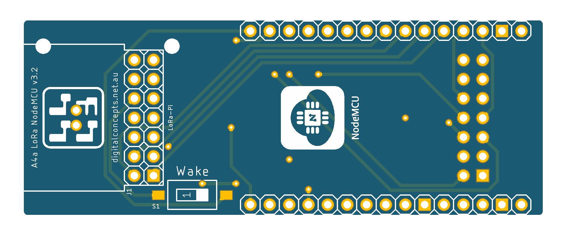
The various elements are identified in the board schematic and laid out as illustrated below:
| Top | Bottom |
|---|---|
 |
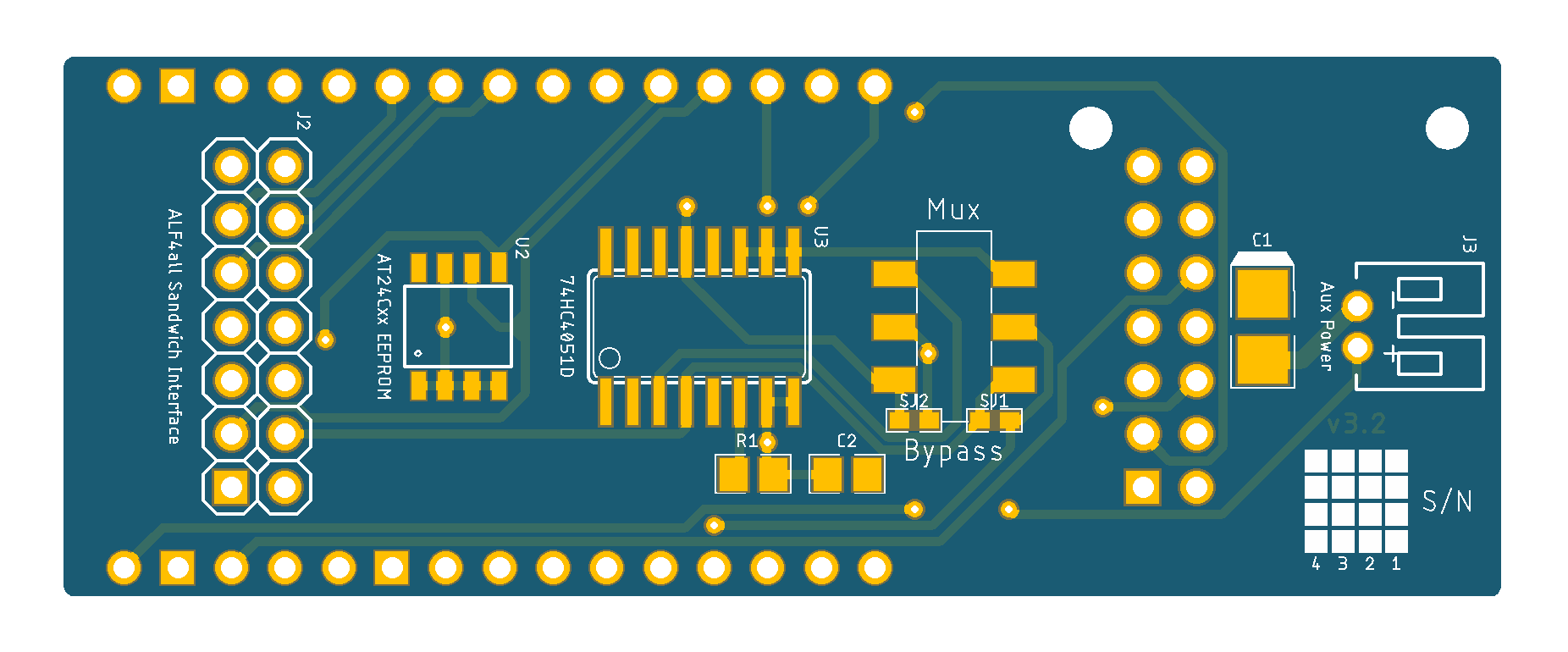 |
A4a LoRa NodeMCU [v3.2] PCB
See here for CAD and CAM files.
While essentially functionally identical, this board layout is somewhat simpler than that of the ESP-12 board because many of the basic functions, like the serial interface, pull-up and pull-down resistors, and voltage regulation, are included on the NodeMCU Dev Board itself.
Configuration
Basic Configuration
With the obvious exception of the processor itself, almost all of the components on this board are optional. The NodeMCU module itself includes everything needed for programming and basic operation.
Processor
- Two 14 Pin Straight Female Headers
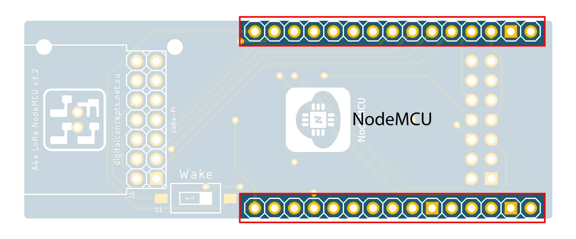 |
NodeMCU Module
Note that, while the NodeMCU is an Open Hardware platform, not all modules are exactly the same size—refer to this article for some of the more specific details. I have used the Amica NodeMCU module throughout.
ALF4all Sandwich Interface Header
- 2×7 Pin Straight Male Header (J2)
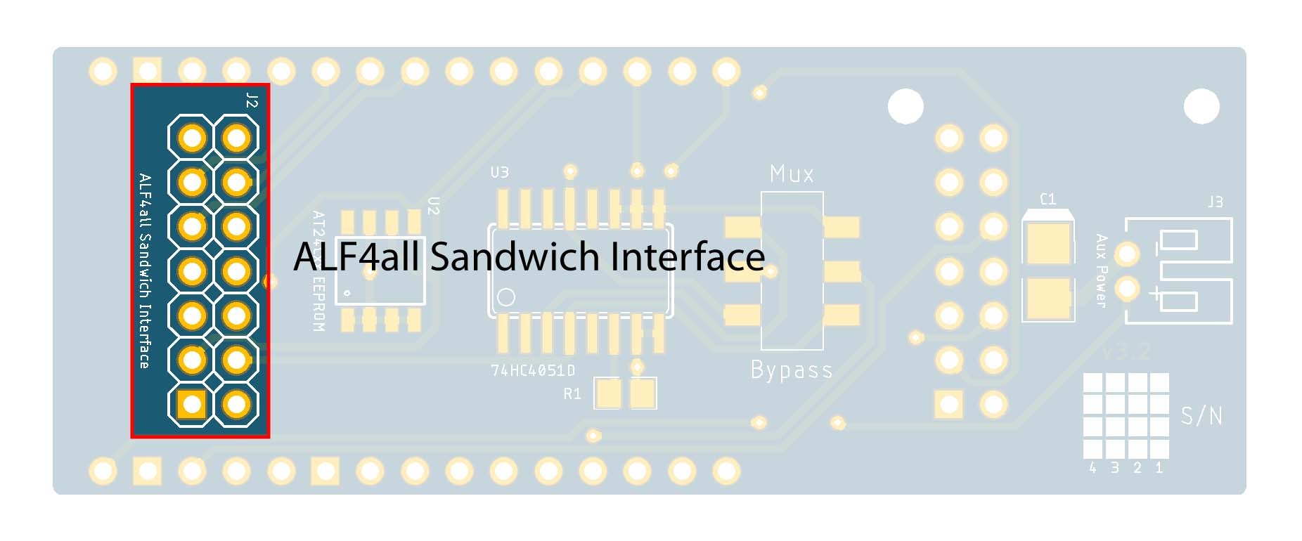 |
ALF4all Sandwich Interface [Male]
All of the A4a processor modules are designed to plug into one of the A4a base boards (8558-BCS-A4a or 10068-BCS-A4a). When configured with one of these power supply/base boards, the processor draws its power from, and connects to relevant sensors through, the base board. These processor modules can, nonetheless, operate independently if they are powered through the auxiliary power connector or, in the case of the NodeMCU board, the onboard USB socket.
Rather than confuse matters by presenting different versions of the A4a Sandwich interface pin configuration that are mirror images of each other, the configuration of the female header on the A4a base boards (e.g. 10068-BCS-A4a) is illustrated below. The configuration of the mating, male header on processor boards is the mirror image of this.
ALF4all Sandwich Interface [Base Board – Female Header] Configuration
Optional Elements
While the A4a LoRa NodeMCU board can operate with only the above components, the following can also be configured for added functionality.
EEPROM
- AT24Cxx (02–64KB) SOP-8 EEPROM (U2)
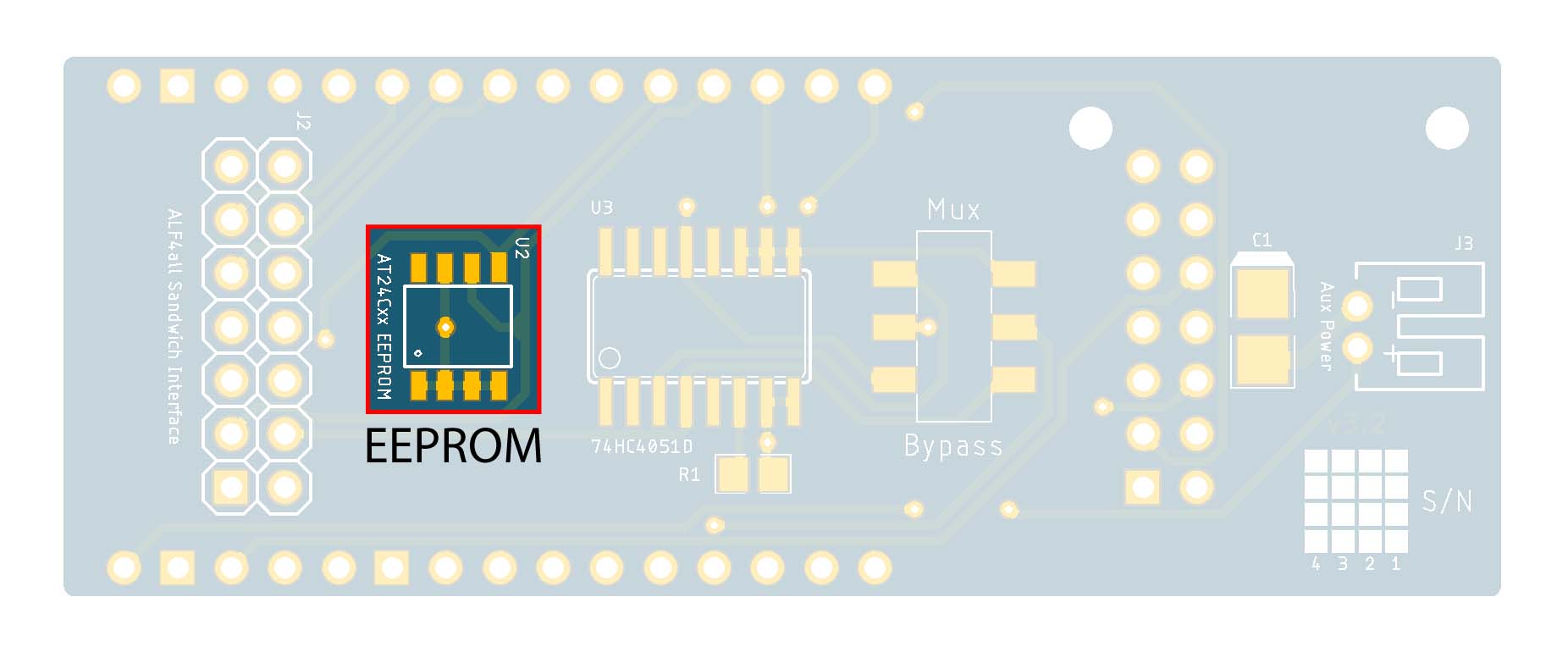 |
EEPROM
As it stands, ESP8266 modules don't have genuine onboard EEPROM memory, although this function can be emulated in part (512 bytes) of the module's flash memory.
Regardless, all of the A4a LoRa processor boards include support for an I2C EEPROM, providing a level of consistency with how any processor or node information that needs to survive a power cycle can be managed.
At the moment, the only common inforation stored in EEPROM is a number, the Sequence Number, that is used to keep track of the sequence of LoRa transmissions. The 'weather station' application also uses the EEPROM to store rainfall data. Nonetheless, this data storage option exists for any future application that may need it.
Pull-up resistors are not required in this case as they are included on the NoceMCU module itself.
Auxiliary Power Connector
- 2P PH2.0 Right Angle JST Connector (J3)
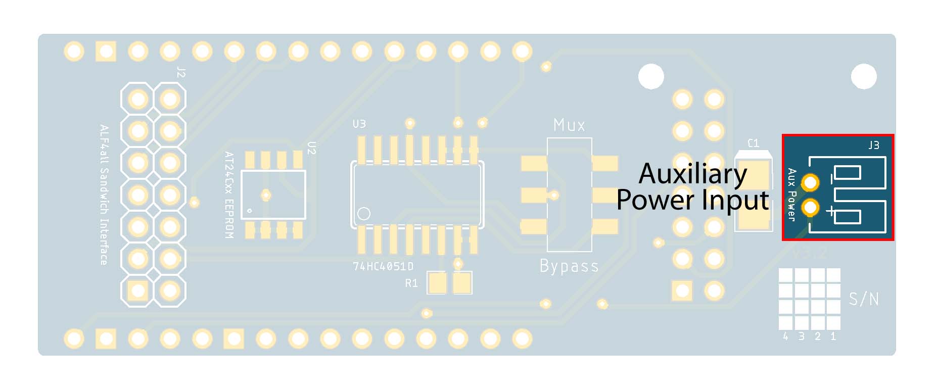 |
Auxiliary Power Connector
The auxiliary power PH2.0 connector feeds into the VIN pin on the NodeMCU module, which in turn feeds into the NodeMCU onboard voltage regulator. With its own, onboard regulator, the NodeMCU Dev Board can be powered through the VIN pin by any source in the range 4.5–10V.
Some sources suggest that any supply used to power the NodeMCU Dev Board must be at least 4.5V, and that the 3.3V pins on the module are only for power output, but I have had no trouble powering the module with a regulated 3.3V supply (from a 10068-BCS-A4a power supply/base board) through one of the 3.3V pins.
Analog Multiplexor
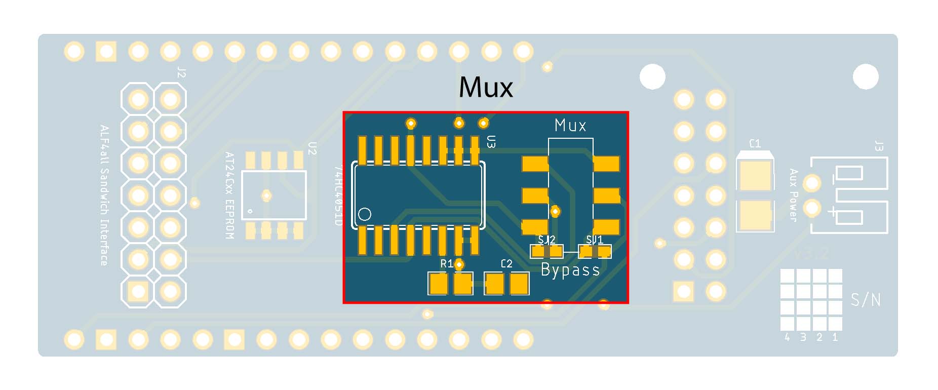
- 74HC4051 SOP-16 8-Channel Analog Multiplexer (U3)
- 2P2T SMD Switch (S2)
- 0.1µF 0805 Capacitor (C2)
- 10kΩ 0805 Resistor (R1)
Only two channels used but, even so, this was the most cost effective option.
 |
Analog Multiplexor
Since the ESP-12 processor on the NodeMCU module includes only a single ADC, the analog multiplexor can be used to switch between two separate analog sources. An 8-channel multiplexor has been used simply because it was the most economical solution, even if only two channels are being used.
In this configuration, two processor pins are required: the ADC pin (the A4a A0 pin) and a digital pin (the A4a A2 pin, SD3 on the NodeMCU) to set the mux address (0 or 7). If two analog sources are not required, the Mux Bypass Switch provides the ability to switch the mux out of the circuit so that the [digital] address line (A4a A2) can be used for other purposes.
If the mux and Bypass Switch are not configured, and the ADC or SD3 (GPIO10) are to be used, the two solder jumpers SJ1 & SJ2 need to be bridged.
There is much discussion in various quarters about whether or not it is appropriate to be using GPIO9 and GPIO10 on the ESP-12E/F processors (SD2 & SD3 on the NodeMCU), as they have specific and, in some cases, exclusive internal functions. For my own part, in my testing, I have had no success using GPIO9 (SD2) for external functions, but no problem using GPIO10 (SD3).
LoRa-Pi Header
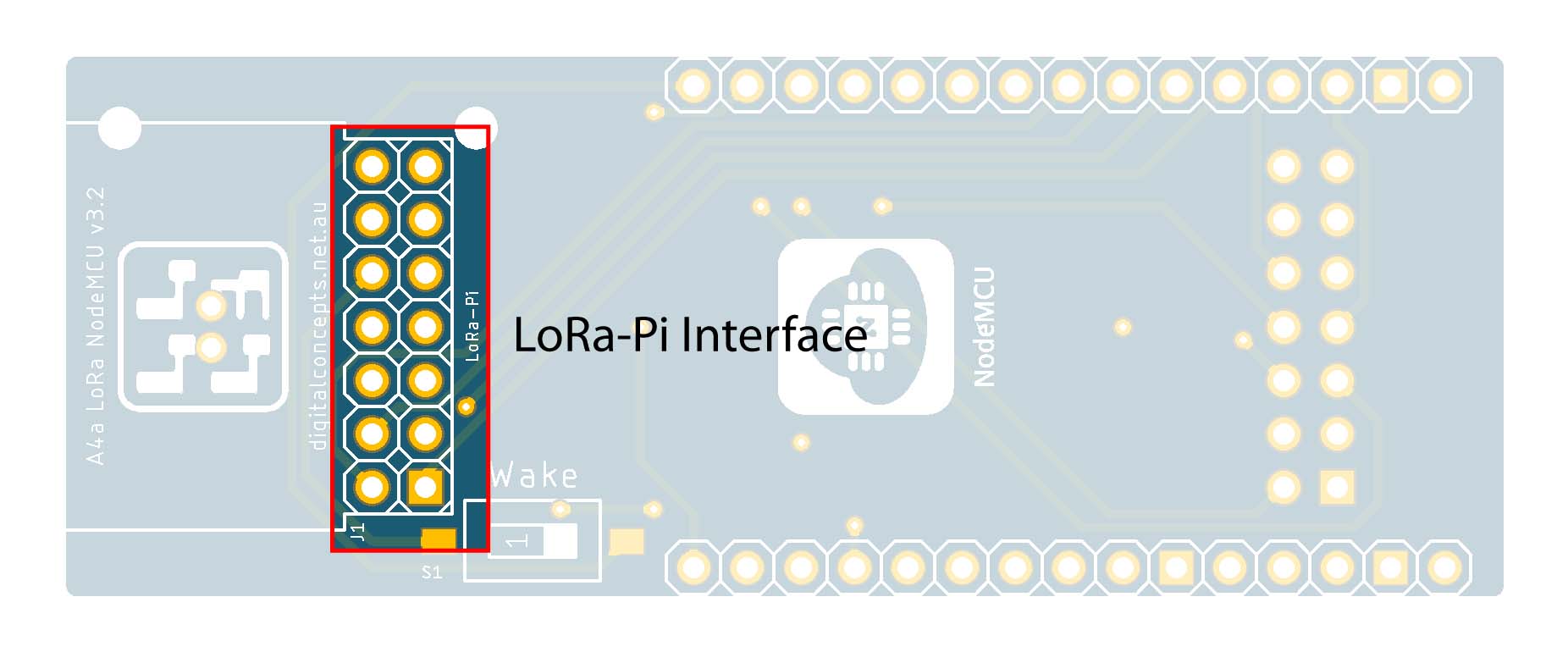
- 2×7 Pin Straight Male Header (J1)
 |
LoRa-Pi Header
For my prototyping work, I have used my LoRa-Pi Hat to interface with the RFM95W radio that is used with processors—Espressif or Arduino (Atmel)—that do not include an onboard radio. The simple reason is that this allowed me to create many configuration variations without having to use a new radio module for every one, rather just swapping the Hat between configurations. The configuration of the RFM95W pins on the LoRa-Pi interface is simply that which allows direct connection to a Raspberry Pi [male] header—the LoRa-Pi Hat, itself, thus has a female header—using the Hallard pin configuration. The LoRa-Pi interface header on the A4a processor boards is thus also a male header, configured as illustrated below.
LoRa-Pi Interface [Processor Board – Male Header] Configuration
Refer to the LoRa-Pi Hat page for the full details of its hardware configuration.
Power Conditioning Capacitor
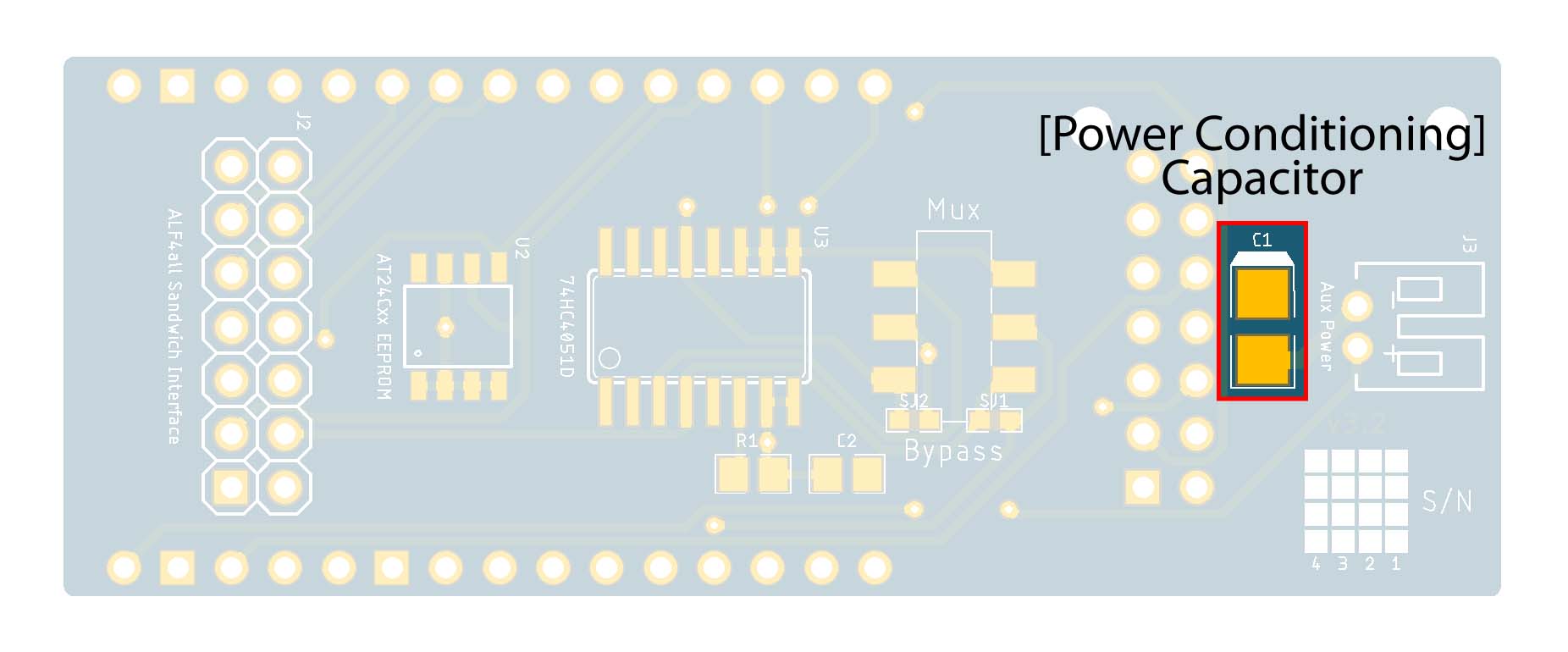
- 220µF 3528-21 Tantalum Capacitor (C1)
 |
Power Conditioning Capacitor
At one point, I encountered a problem with the RFM95W radio when coming out of deep sleep (on both this and the ESP-12 board). It was never entirely clear what the problem was, but one of the suggestions I found was that it might be the result of power supply instability. Whether or not this was the problem I was experiencing, I have not had any further trouble since configuring a capacitor across the supply lines as illustrated.
Wake on Interrupt
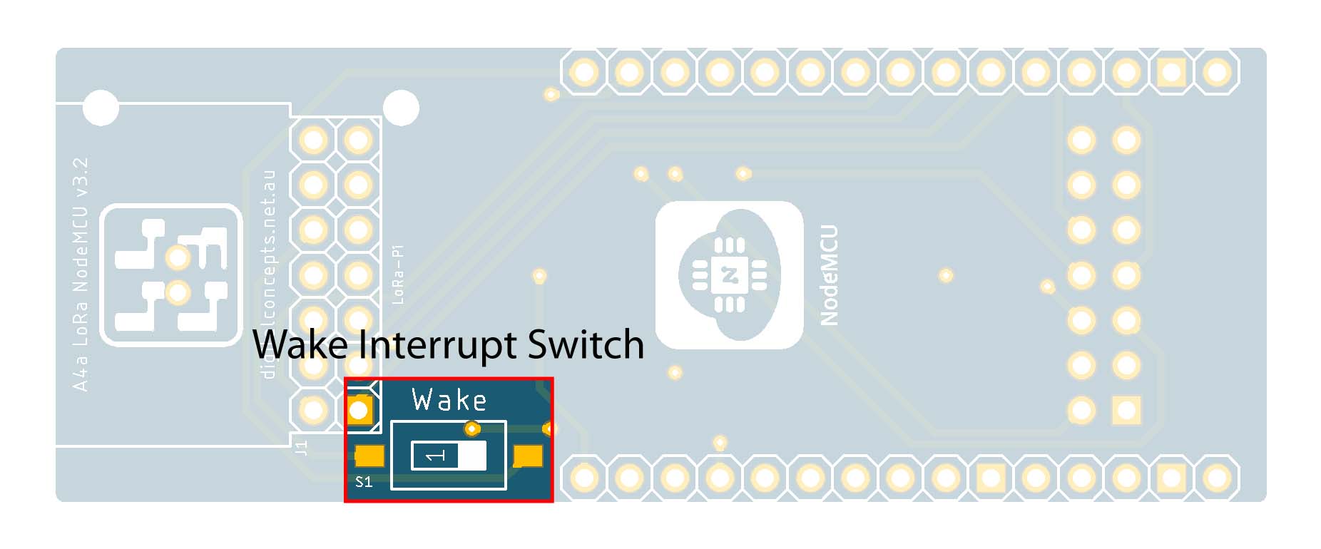
- 1P SMD DIP Switch (S1)
 |
Wake on Interrupt Switch
The NodeMCU ESP-12 will wake itself up on deep sleep timer expiration if RST is connected to D0 (GPIO16). This connection should only be made, however, after the relevant software has been loaded into the processor. The Wake switch is included to support this option but must, therefore, if configured, be turned off when loading software.


