IoT Board Assembly
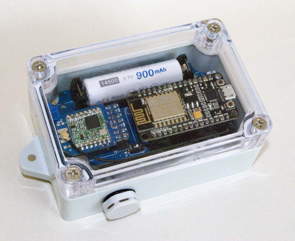
I will add assembly details for each board, and list them in the menu at left, as I manage to prepare them. In the mean time, if anything's unclear, please just post a request on the Forum.
A Candid Confession
I must make a confession right up front. As noted elsewhere on this site, I have absolutely no qualifications as an electrical engineer. My education in this regard is limited to a first year university physics course, back in 1973 (yep, that also dates me) that included a few lectures and one lab session on electronics. This has been followed up by a lot of reading in more recent years.
I make this confession by way of explanation for anything I've done that looks silly to a more experienced eye. Most of the circuit segments that I have included in my various projects have been unashamedly copied from the work of others more knowledgeable in the subject than I, often with only as much understanding on my part as was necessary to make the circuit elements 'work' in my environment.
I have, however, endeavoured to provide references to the sources for all of the circuit elements that I have used so, if something looks silly, the reader should at least be able to see why that might be so.
Tools of the Hobby
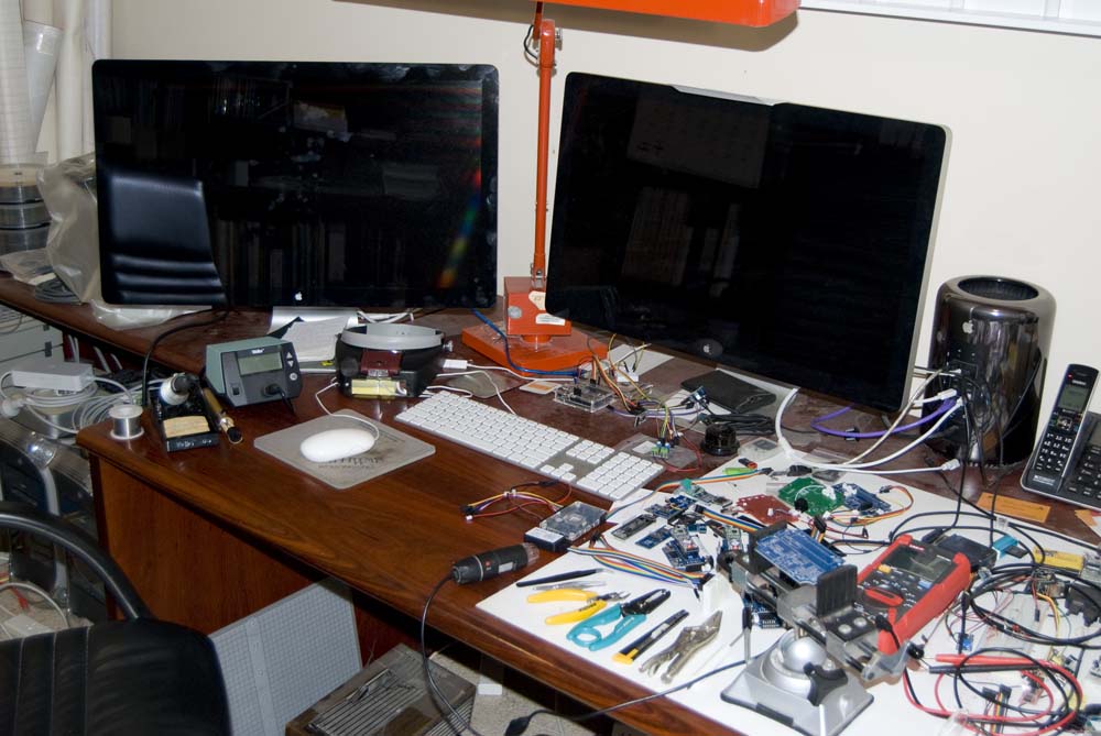
So far, I've managed to do all of my work on a regular, somewhat cluttered desk with a fairly basic set of tools.
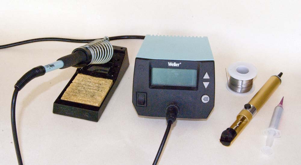
I use a Weller WE1010 soldering station with an 0.8mm tip for most of my work, either through hole or surface mount. I do have a hot air rework unit, but I'm yet to need to use it for anything more than warming heat shrink tubing. I generally use solder paste, from a syringe, for surface mount components, at least for the initial location of the components—with only two hands, it's easier to hold the component while soldering if I don't also need to be holding solder wire.
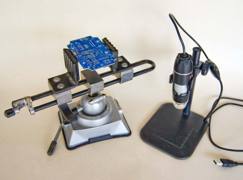
I use a PanaViseModel 380 desk vice to hold my work, and a cheap digital microscope to check component markings, soldering joints and the like.
I generally use a pair of head-mounted magnifying glasses when soldering. I did try to solder under a binocular microscope but, while it was nice for things to be so big and clear, it ended up being more mucking around than it was worth—I could see everything I needed to see with my magnifiers.
Testing
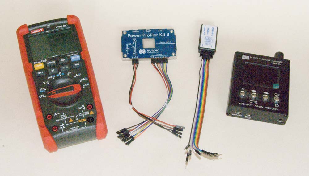
On the testing side, I have a regular multimeter and a Nordic Power Profiler Kit II, the latter mainly used for low current measurements, and a cheap logic analyser that runs the [free] Saleae Logic2 software. I also have an N1201SA antenna analyser, but I really only used that to identify a reliable source for the antennae that I use and it's pretty much idle these days.
One other tool that came in handy when troubleshooting hardware configurations (because I rarely managed to translate my breadboard configurations into PCB layouts perfectly the first time around) was a breakout board that allowed me to tap into various wired connections using JST or RJ connectors. To this end I created a custom PCB that broke out the pins in the range of connectors that I was using (see board schematic).
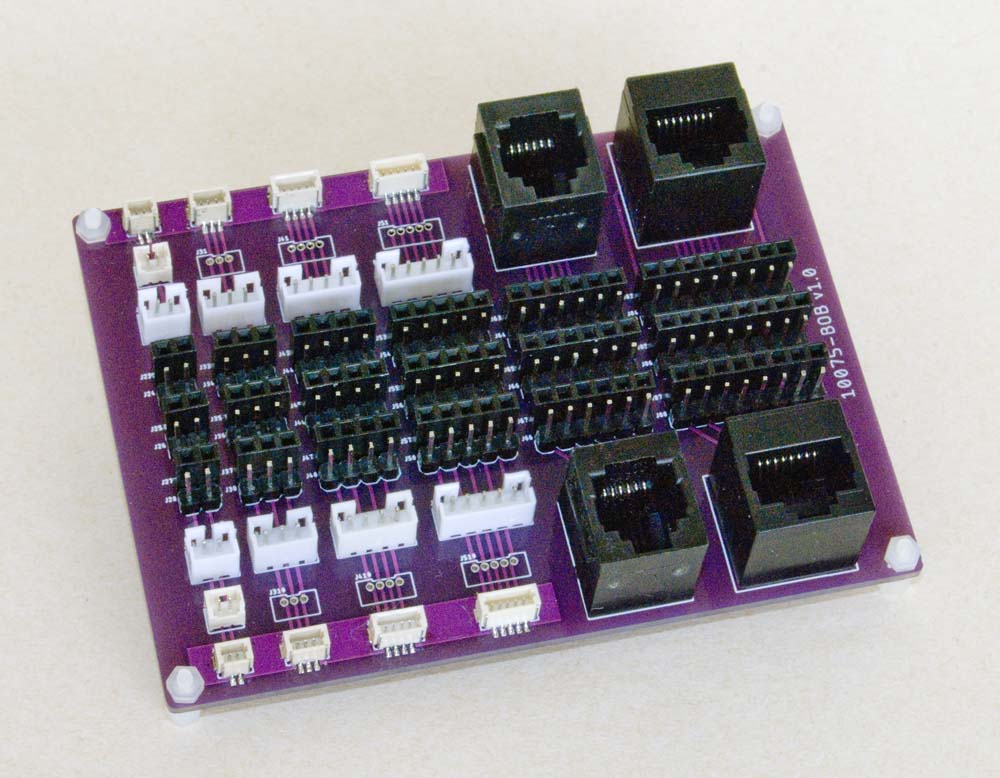
[10075-BOB] JST/RJ Connector Breakout Board

|
100x75 BOB Eagle CAD Files | [36 KB] |

|
100x75 BOB CAM Files | [132 KB] |
In relation to the components on this breakout board, the JST connectors are generally the same, regardless of source, but there are many different styles of RJ connector. The pins are always in the same relative positions, but the mounting lugs can vary slightly in size and location. The ones that I generally use, illustrated below, can be purchased through AliExpress.
.jpg)
RJ 180° Vertical Female Sockets
There are really no other 'tricks', other than a steady hand and a bit of patience (especially when things don't work the way you think they should), that I've had to employ in my work, or play, to date.
Materials
Declaration
I get no kick-backs from anyone for any of the comments or recommendations I make on this site.
Components
I have sourced most of my components through AliExpress. I make no particular effort to choose suppliers who may or may not provide a better product. For the most part, I have simply chosen the supplier with the best price—this is, after all, just a hobby for me—but this often only relates to shipping costs in any case. I have had a few problems along the way, with both product quality and shipping, and where these are relevant I have offered an appropriate comment.
I tend to buy at least two of anything, and that's always been enough to identify any faulty component that I have encountered. At the end of the day, I accept that you generally get what you pay for and the need to buy a few spares is cheap insurance.
I will ultimately provide a complete Bill of Materials for each of the boards I describe, but this will take a little time and is not my top priority, so please be patient. For the most part, you should be able to find anything by just using the description I have provided and searching AliExpress.
PCB Fabrication
I use JLCPCB for all PCB fabrication. The service is good, the prices are competitive, the range of production options more than I need and I can't fault the quality of the product. I invariably just upload the CAM files that I have provided in these pages, choose the desired PCB soldermask colour, and that's it. The boards generally turn up on my doorstep (in Australia) about 10 days later.
For a single board, I pay around A$2.20 (A$11.00 for 5, including shipping), and that price comes down to about A$1.50 if I order more than 5 boards or more than a single board design (i.e. 10 or more boards) in a shipment.

