

8558-BCS-A4a PCB

The BCS-A4a (Battery-Charger-Solar, with ALF4all sandwich interface) boards (8558 and 10068) are prototyping boards designed as power provision and sensor support platforms for a range of processor modules that are connected through the 2 x 7 pin ALF4all 'Sandwich' interface, which breaks out SPI, I2C and serial Tx/Rx pins, as well as four (A0 – A3) control pins. My original intention was to use the smaller, 85 × 58 enclosure for my applications but as things progressed it became apparent that was going to be too small to accommodate all but the most simple configurations. I do, nonetheless, use this board in conjunction with the Arduino Pro Mini processor from time to time, so I have continued to update it in line with applicable developments made to the larger board.
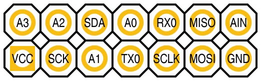
ALF4all Sandwich Interface Configuration
The 8558-BCS-A4a board is ow very much a cut-down version of the 10068-BCS-A4a board, designed to fit within the smaller 85 × 58 enclosure. As a result of the constraints of the smaller enclosure, many of the options provided in the larger board are not included and those that are must be chosen or bypassed through the physical bridging of solder jumpers rather than simply flipping DIP switches. While much of my more recent development work is more focused on more specifically designed boards, I still use the BCS-A4a boards to test software on the Arduino Pro Mini platform and the 8558 version is the neatest packaging in this case.
Board Layout
The various subsystems are identified in the board schematic and laid out as illustrated below:
| Top | Bottom |
|---|---|
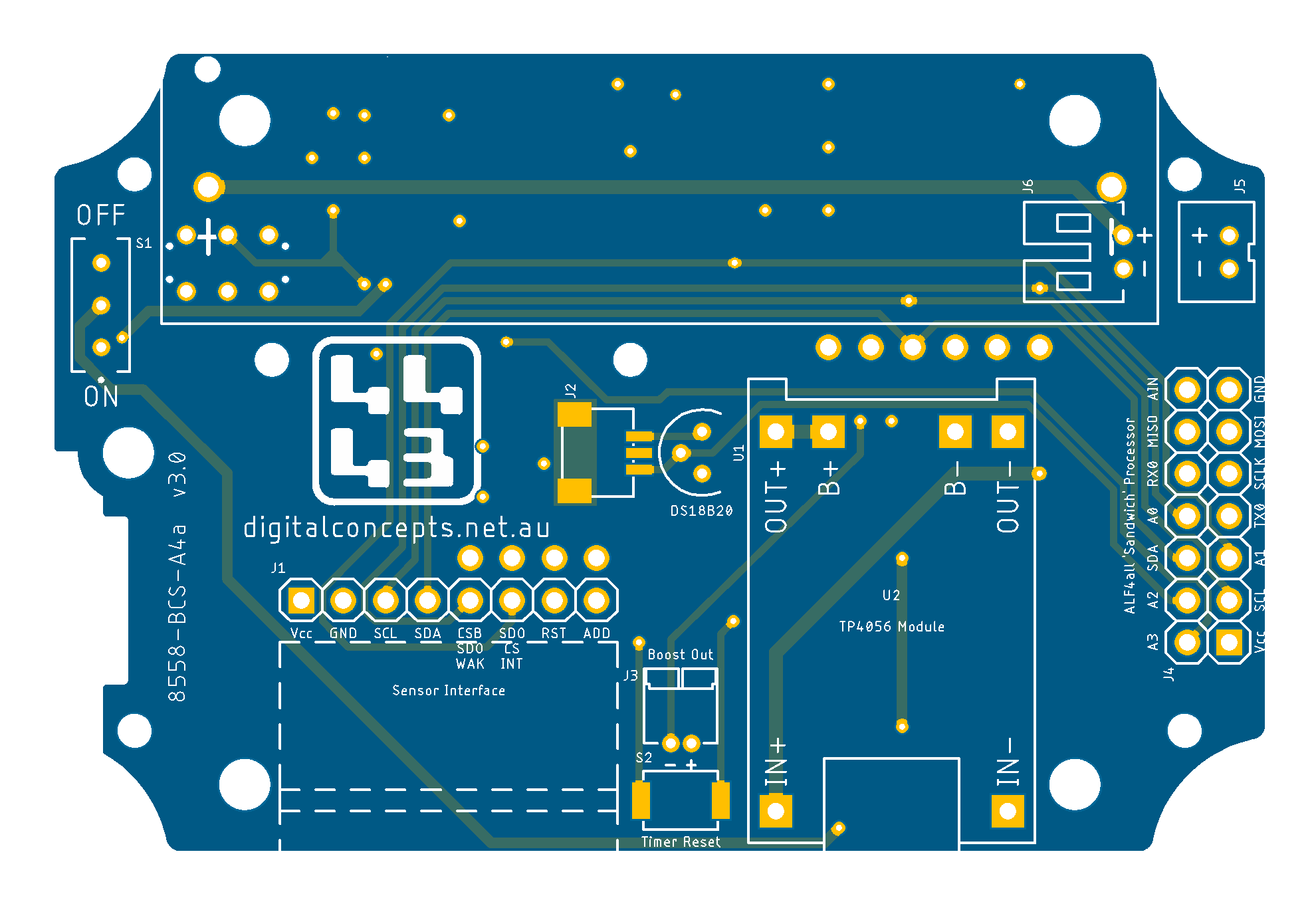 |
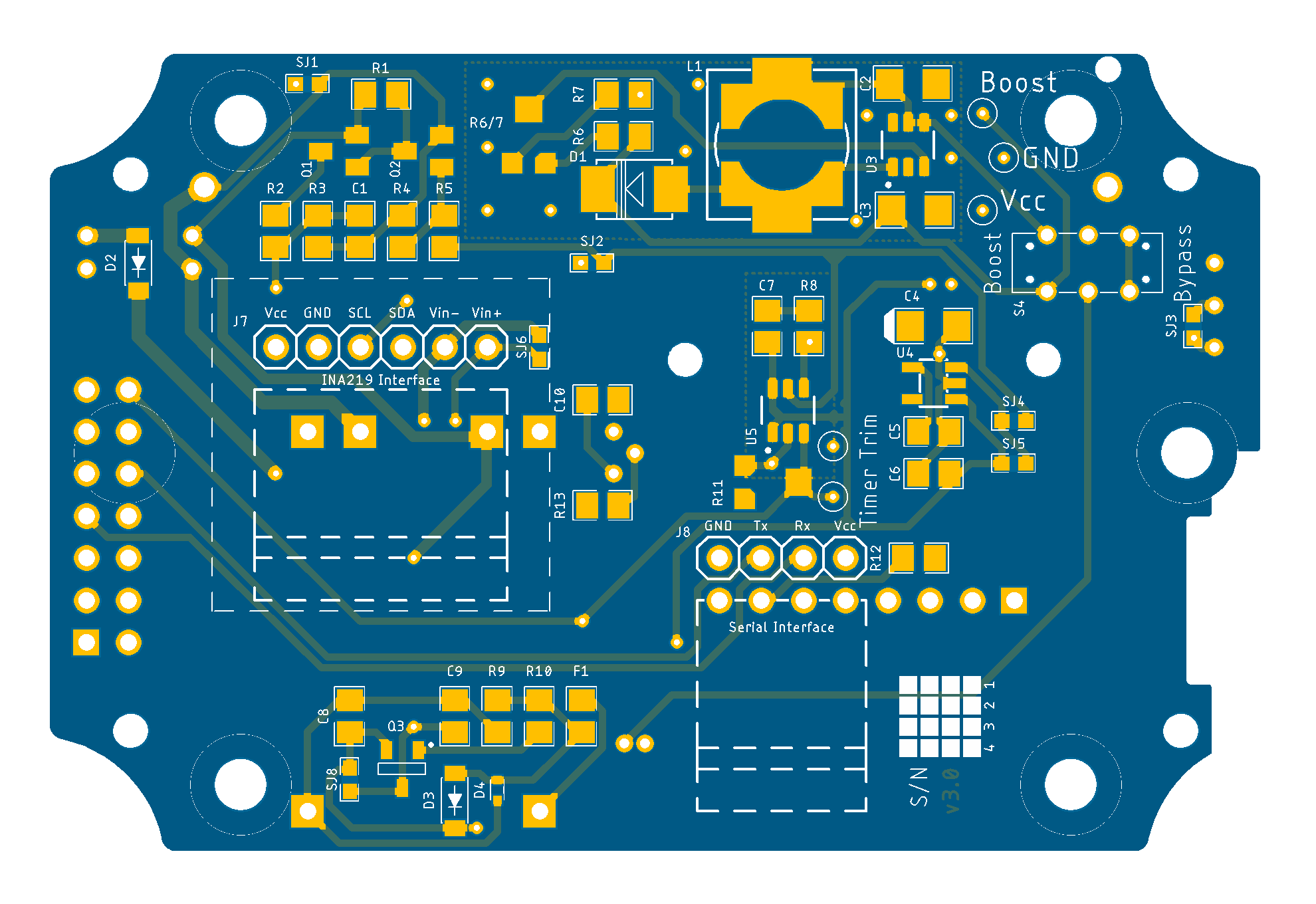 |
8558-BCS-A4a [v3.0] PCB
See here for CAD and CAM files.
Basic Configuration
The most basic configuration of this board, like the larger format 10068‑BCS‑A4a board, requires little more than connecting a battery to a [ALF4all Sandwich] processor and required sensor interface(s).
Battery Connection
Once again, there is insufficient room in the smaller 85 × 58 enclosure to accommodate an 18650 battery—this board is limited to either a 14500 battery holder (B1) or a JST PH2.0 connector (J9) to support LiPo batteries.
Solder Jumpers
| Top | Bottom |
|---|---|
 |
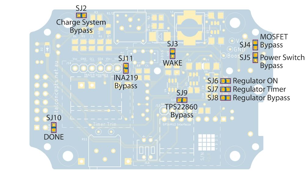 |
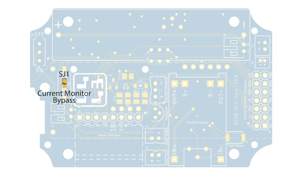
[v3.0] Solder Jumper Locations
Note that specific solder jumpers will generally need to be bridged to bypass unused circuit elements.
Solder Jumper Functions
The functions of the various solder jumpers are listed below. When a jumper is bridged, the listed function is active (e.g. when the Current Monitor solder jumper is bridged, the Current Monitor circuit is bypassed—a DIP switch option is provided for the Current Monitor: the ON position is equivalent to a bridged solder jumper), otherwise the listed function is inactive.
Solder Jumper Functions
| Solder Jumper | Function |
|---|---|
| SJ1 | Charge System Bypass |
| SJ2 | A1 Circuit (WAKE signal) |
| SJ3 | Power Switch Bypass |
| SJ4 | MOSFET Switch Bypass |
| SJ5 | Regulator Enable - Always ON |
| SJ6 | Regulator Enable - Timer Controlled |
| SJ7 | INA219 Bypass |
Power Switch
As noted above, power supply to the board can be configured permanently by bridging the solder jumper SJ5 or controlled via a switch (as illustrated).
Photo to be supplied
Power Switch & Remote Power Switch Connector
A 2P JST PH2.0 connector can also be configured to allow connection to a power switch on a secondary board. This connector can actually be configured either vertically on the top or horizontally on the bottom of the board.
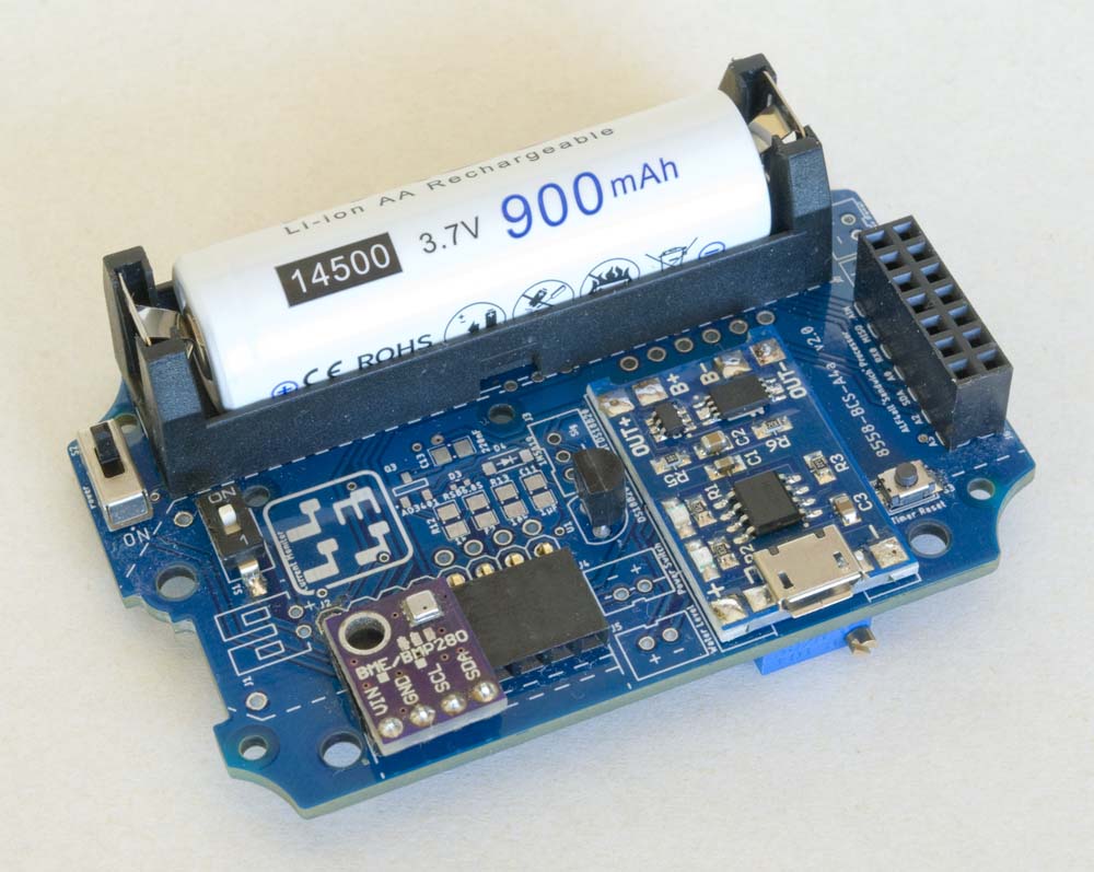
Configuration Options
 |
 |
Battery/Charge/Sensor Base Board
Apart from the various battery configurations, and the ALF4all 'Sandwich' processor interface, the boards can be configured with a subset of the optional features available on the 10068-BCS-A4a board:
- TP4056 battery charge management modules
- battery voltage and current monitoring circuitry
- solar panel input
- step-up boost converter
- low power timer circuitry and voltage regulator
- timer reset button
- DS18B20 digital temperature sensors
- I2C interface
- INA219 interface
- Serial interface
Battery Charging Circuit
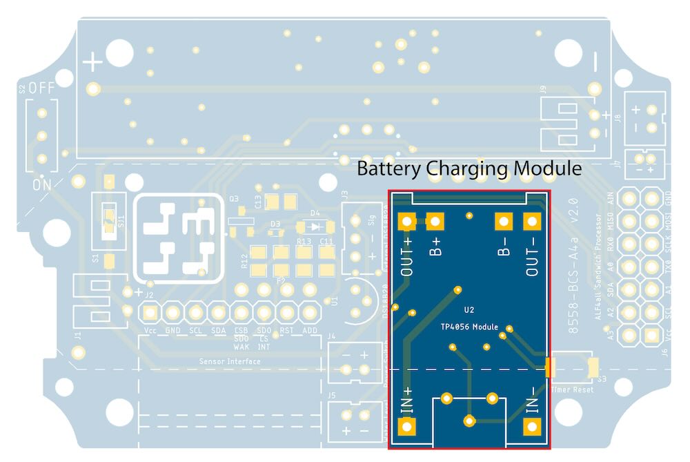 |
Battery Charging Module
Comment about initially accommodating both TP4056 and TP5000 options but now just TP4056 given the choice to go with Li-Ion battery technology rather than LiFePO4.
Note that the battery charging module is only really required if the Node is also to be configured with a power source that can be used to charge the battery. In the present case, the only external power source, apart from the USB connection on the charging module itself, would be a solar panel. Accordingly, if the Node is not to be powered through the charging module itself and a solar panel is not being configured, the charging module is not required and can simply be bypassed by bridging solder jumper SJ2.
Battery Voltage Monitor
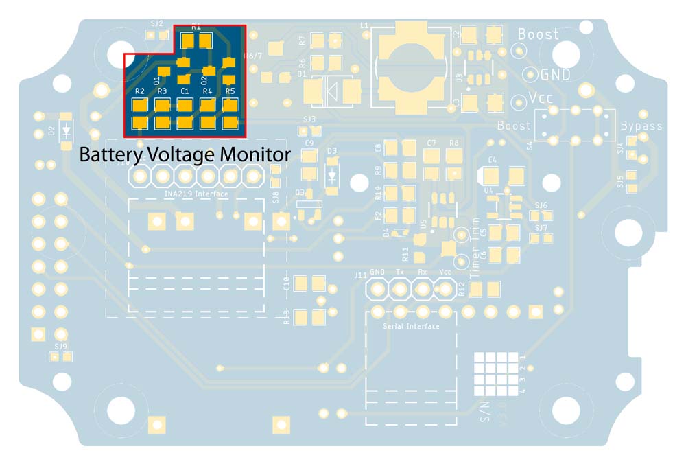 |
Battery Voltage Monitor Components
Used to monitor battery voltage, this is effectively a voltage divider that is controlled by a pair of MOSFETs—BSS84 (Q3) & BSS123 (Q4)—so that it can be switched on only when required, avoiding the quiescent current leakage normally associated with an active voltage divider.
Brief words with reference to 10068 version for detail if required
Solar Panel Power Input
Photo to be supplied
Solar Panel JST PH2.0 Connector
Solar panel connectivity is provided through a 2P JST PH2.0 connector (J14) configured in conjunction with a 1N5819 Schottky diode (Z2) for reverse current protection of the solar panel.
Brief words with reference to 10068 version for detail if required
MT3608 Boost Converter
Photo to be supplied
Boost Converter Circuit Elements
The MT3608 (U4) boost converter circuit can be configured to provide a 3.3V-28V power source or bypassed, or simply not configured, as required.
Brief words with reference to 10068 version for detail if required. Note use of smaller, less sensitive trimpot based on space constraints.
'Tap points' are provided close to the boost converter circuit to facilitate the setting of the boost converter output voltage—assemble the circuit then use a multimeter to measure the Boost–GND voltage while adjusting 10kΩ trimpot (R5/6).
Photo to be supplied
Voltage Measurement Points
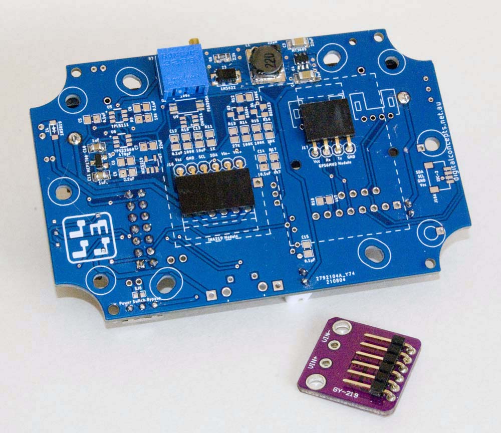
The boost converter output, or simply the battery output if the boost converter is bypassed, is connected directly to the 2P JST2.0 [Water Level] connector and then to the INA219 module that is plugged into the 6P header on the base of the board. The INA219 module is thus used to measure the current in this circuit.
 |
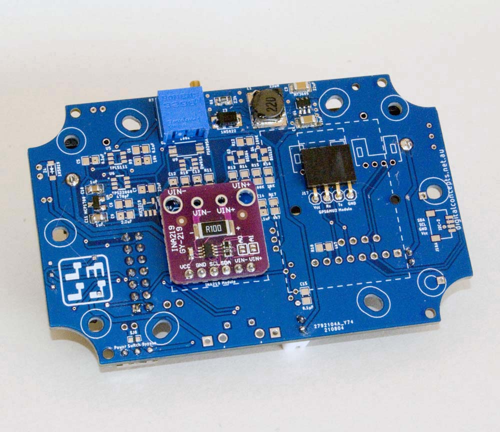 |
INA219 Module
Photo to be supplied
Boost Converter Output JST Connector
This interface was originally included to support an HDL300 water pressure sensor. In practice, as previously noted, the 85 × 58 enclosure is not big enough to house all of the components and connectors required to support this application but I've left these elements in place to provide output for the boost converter in any case. The original application also involved 4-20mA current measurement in the circuit, achieved through the inclusion of an INA219 voltage/current sensor module with I2C interface. Again, I've left this component in place the left-most four pins of the header present I2C interface on the board and can therefore be used for any I2C device. Similarly, the boost converter can be used to power any sensor that requires anything from the 3.3V input voltage to around 30V in its present configuration.
Once again, refer to the assembly notes for the 10068-BCS-A4a board for more detail.
TPL5111 Timer
The TPL5111 timer and MIC5219 regulator can be configured in combination to provide a low power option that can be used to cut power to the processor and sensors between sensor readings and packet transmissions.
TPL5111 Timer
Photo to be supplied
TPL5111 Circuit Components
The TPL5111 Timer (U5) can be configured, with or without the MIC5219 regulator or all of these components omitted altogether, to suit the application at hand.
An optional reset button can also be configured to manually trigger and reset the timer.
Photo to be supplied
Timer Reset Button
Voltage Regulator
Either of two [3.3V] regulator options can be configured if required—no regulator is required, for example, if using a LiFePO4 battery. The early versions of the BCS boards only used the MCP1700 regulator. The MIC5219 option was added with the timer elements because it could be switched off when not in use. Both options remain because the MCP1700 is a simple 'set and forget' alternative when that is all that is required.
The voltage regulator circuit can be configured or bypassed as desired, independently of the timer/switch circuit. By default, the regulator circuit is 'in circuit'.
MIC5219 Voltage Regulator
Photo to be supplied
MIC5219 Circuit Components
The MIC5219 regulator (U7) is a low dropout linear voltage regulator that can be enabled or shut down by an external trigger signal. This regulator circuit, which includes capacitors C8 (470pF) and C9 (2.2µF), is thus activated by the timer circuit to minimise quiescent current leakage.
Sensor Configuration
ALF4all Sensor Interface
The main sensor interface is provided through an 8-pin female header configured in accordance with the Wijnand Nijs ALF4all sensor interface. It supports a range of sensors, using several different interace configurations, including any that use an I2C interface (left-most 4 pins of the header).
Photo to be supplied
ALF4all Sensor Interface Configuration
Photo to be supplied
ALF4all Sensor Interface
Note on right angle headers
Serial Interface
Photo to be supplied
Serial Interface Header
I2C Interfaces
Photo to be supplied
I2C Connection Points
DS18B20 Temperature Sensor
Photo to be supplied
Photo to be supplied
DS18B20 Components
Photo to be supplied
DS18B20 Sensors
There are two varieties of this digital temperature sensor, one (the 'internal' version) that can be soldered directly to the PCB, in the space allocated, and the other (the 'external' version) that can be configured to plug into a 3-position JST PH2.0 connector. Both of these options require the configuration of capacitor C14 (0.1µF) and resistor R17 (4k7Ω for on-board sensors or short cables, or 2k2Ω for longer [2-3m or more] cables), in addition to the sensor and/or connector.
Further details pending