

Piggyback Adaptor Boards
Piggyback adaptor boards were developed to accommodate variations in pin configurations on modules that were otherwise intended to use the same parent PCB header. These have been used most often on modules employing an I2C interface, as described in the I2C pages elsewhere on this website.
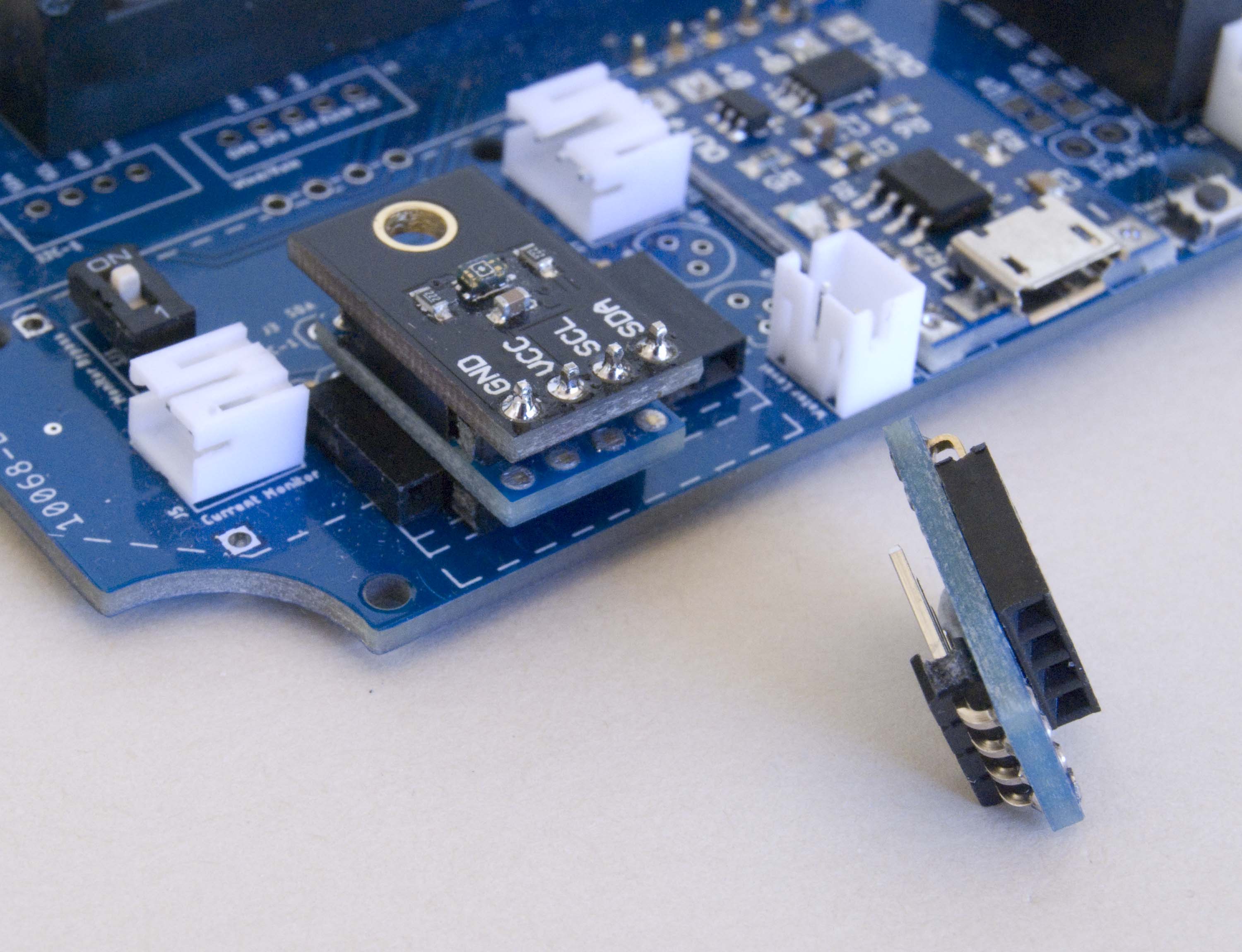
I2C 'Piggyback' Adaptor
| Top | Bottom |
|---|---|
 |
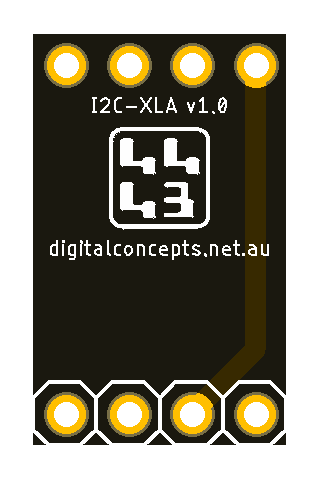 |
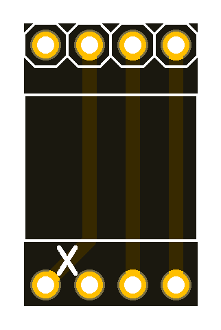
I2C-XLA PCB

|
I2C-XLA Adaptor Eagle CAD Files | [13 KB] |
|
|
I2C-XLA Adaptor CAM Files | [19 KB] |
| Top | Bottom |
|---|---|
 |
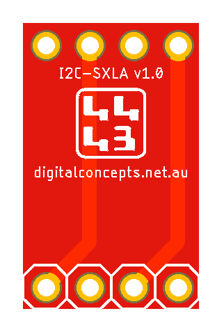 |
I2C-SXLA [SparkFun Adaptor] PCB
|
|
I2C-SXLA Adaptor Eagle CAD Files | [13 KB] |
|
|
I2C-SXLA Adaptor CAM Files | [19 KB] |
The other situation in which a piggyback adaptor has been useful is in using one of the 'standard' headers on a prototyping board for a purpose other than that for which it was originally intended. In this situation, the piggyback board is simply patching the pins of the relevant module into the appropriate prototyping board connections, as is the case when configuring the MPS20N0040D air pressure sensor module described on the relevant sensor page elsewhere on this website.
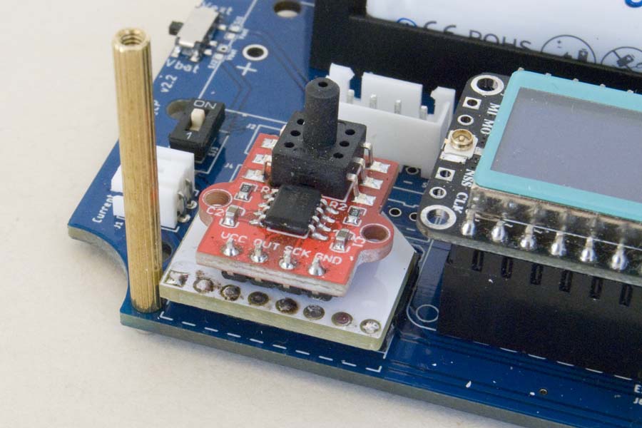
MPS20N0040D Module 'Piggyback' Adaptor
| Top | Bottom |
|---|---|
 |
 |
MPS20N0040D Sphyg-XLA Adaptor PCB
|
|
Sphyg X Link Adaptor Eagle CAD Files | [14 KB] |
|
|
Sphyg X Link Adaptor CAM Files | [20 KB] |