

130 × 95 Boards
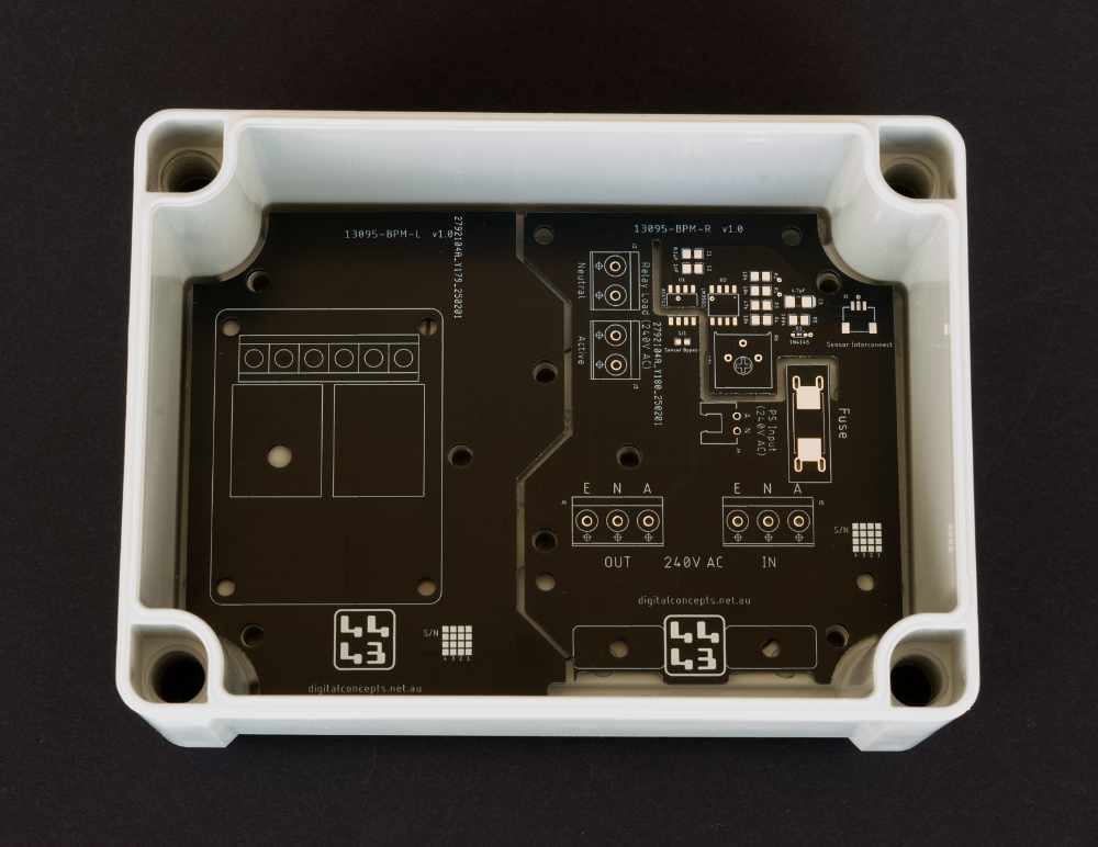
At the other end of the scale, I've more recently had need of a larger enclosure for my pump controller application. In part because I'd used them before, but also because they have no metal parts that rust, I've been using a range of locally sourced NHP N-Line enclosures. They're much more expensive that the ones sourced from China but, as already noted, they don't use any metal parts and looked like they might be better for outdoor applications.
The problem with a larger enclosure, however, is that both Autodesk Eagle, the PCB design tool that I currently use, and JLCPCB, the PCB fabricator that I currently use, limit the size of boards that can be designed [with the free version of the package] and fabricated [at their most economical rate] respectively. Fabrication is less of an issue than the Eagle limitation, because larger PCBs are only marginally more expensive. But it would appear that my original choice of Autodesk Eagle might not have been the wisest, since it would appear that Eagle is no longer being developed and users are being pushed towards Fusion360. The latter is much more powerful but it is 'cloud'-based and not a free standing application. That may not worry some people, but I'm not interested in anything that requires me to store data on a third-party server, nor am I interested in having to pay through the nose (Read: use a third party subscription service) to access my own data.
The upshot of that is that I am currently restricted by my PCB design tool to boards that are no larger than 80 × 100 mm. This left me with two choices when working with the 130 × 95 enclosure: use a PCB that was smaller than the enclosure, or design a PCB in two parts.
That latter option might sound illogical, but the PCB in my pump controller application is as much about providing a base upon which to mount components as it is about providing electrical connections and it turned out that I could indeed conveniently design the base board in two parts.
I did initially design a prototyping board for the smaller, 95 × 65 enclosure, but the board arrangement for my pump controller application, which uses the larger 130 × 95 enclosure, has been designed for that specific purpose from the outset. That application is described elsewhere on this site and the present description is confined simply to that of the PCBs involved.
[13095-BP-L & 13095-BP-R] Base Board [Left & Right]
These, and the 13095-BPHC PCB described below, are specifically designed to support the Power Switch (Pump Controller) application.
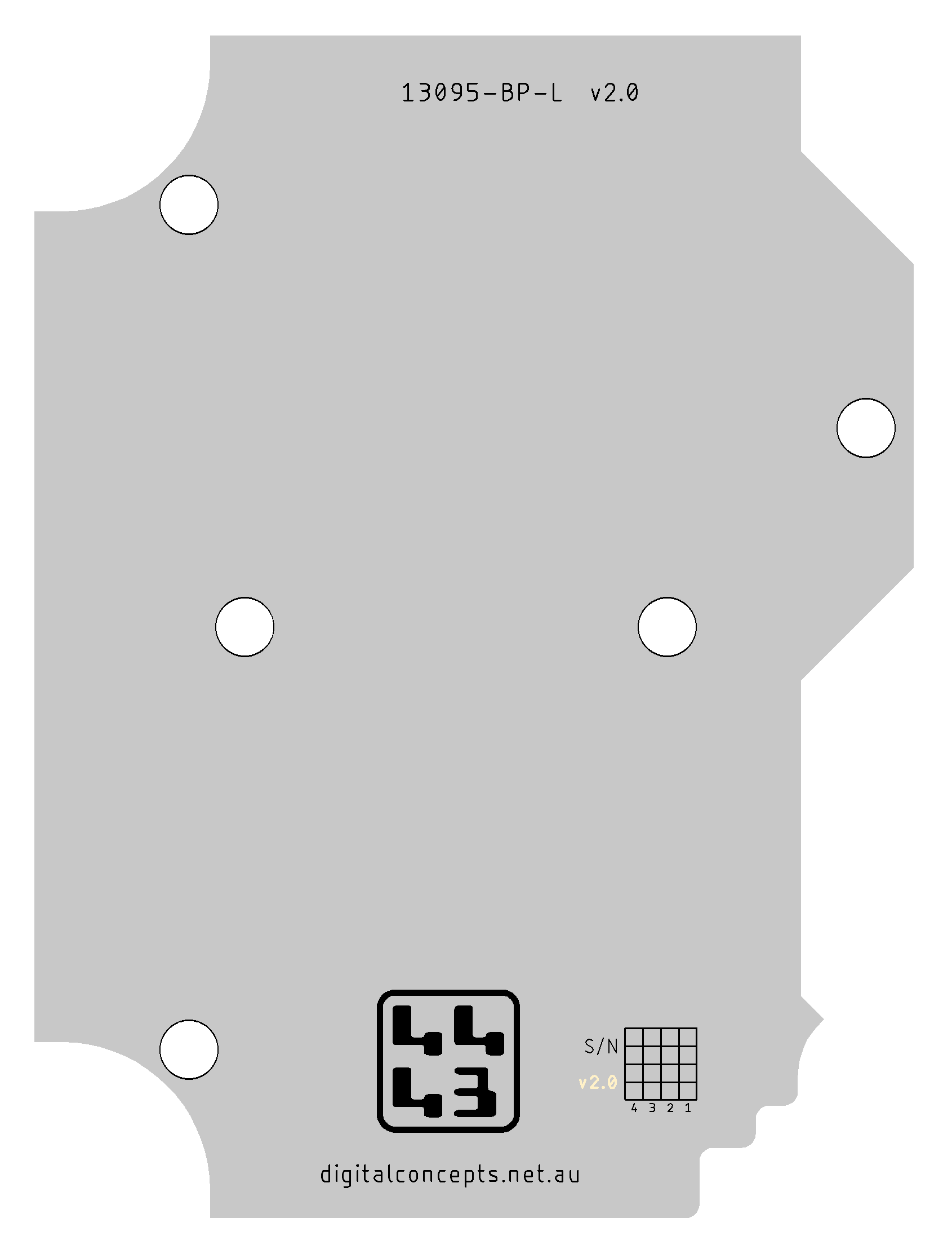
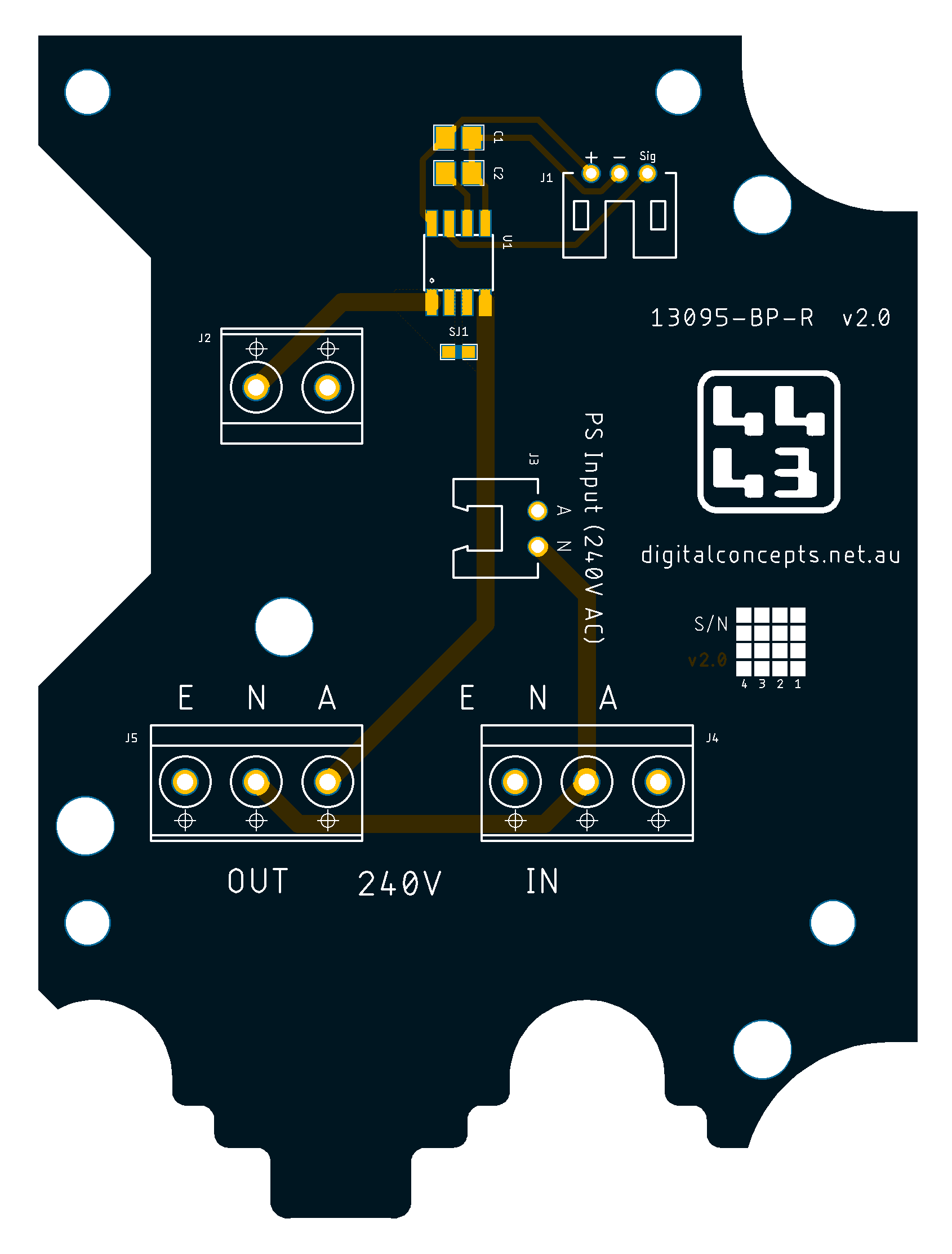
These two boards fit neatly together to occupy the available space within the enclosure—they are designed as two boards simply because a single board would exceed the size restriction for board design with the free version fo Eagle CAD. They are, nonetheless, primarily designed to provide mounting points for components and the secondary 13095-BPHC PCB within the enclosure so there is no requirement for electrical connectivity between the two halves. The left half, which contains no actual circuitry, is fabricated as a PCB simply because this was the cheapest and easiest way to make it. I actually used an option with JLCPCB, my fabricator, to have this board made out of aluminium, providing the added benefit of some element of heat dissipation for the solid state relay it supports.
.jpg)
The cut-outs at the bottom of the boards are to accommodate cable glands and the cables entering the enclosure.
| 13095-BP-L | 13095-BP-R |
|---|---|
|
|

|
13095-BP-L Eagle CAD Files | [16 KB] |
|
|
13095-BP-R Eagle CAD Files | [24 KB] |
|
|
13095-BP-L CAM Files | [38 KB] |
|
|
13095-BP-R CAM Files | [102 KB] |
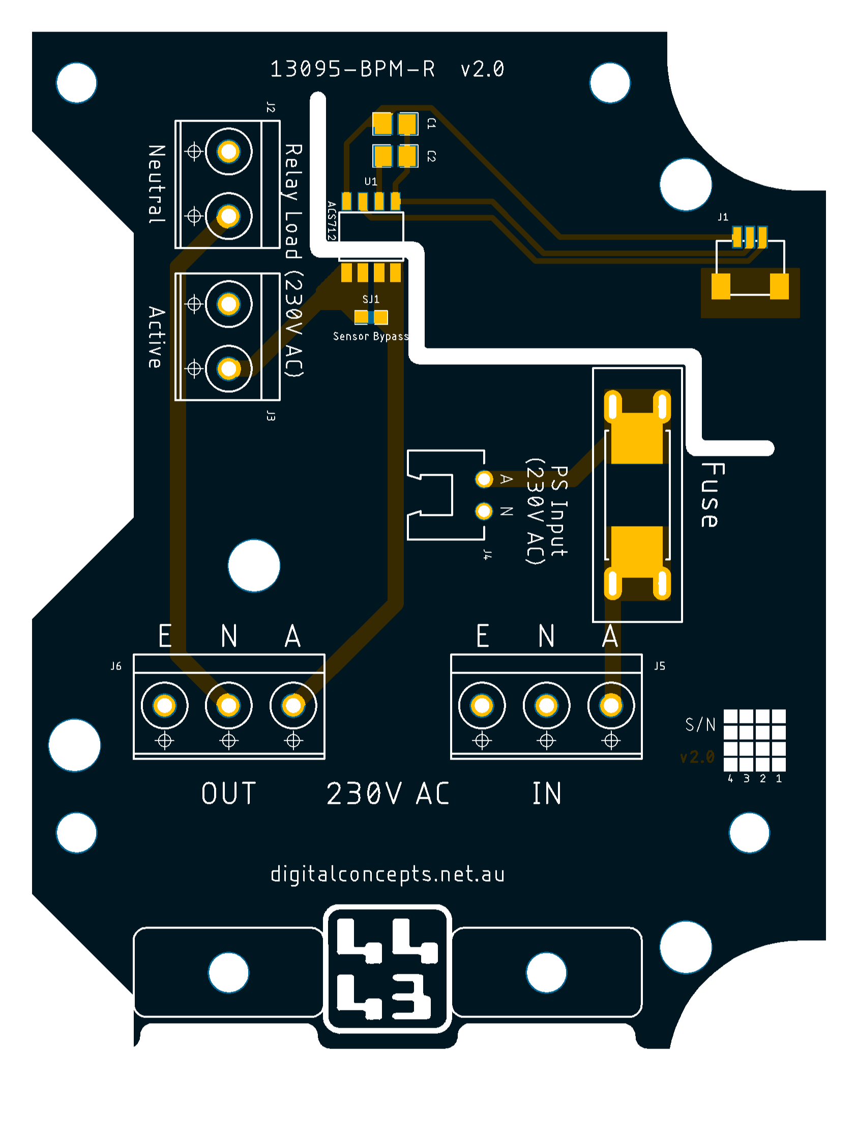
[13095-BPM-L & 13095-BPM-R] Base Board [Left & Right]
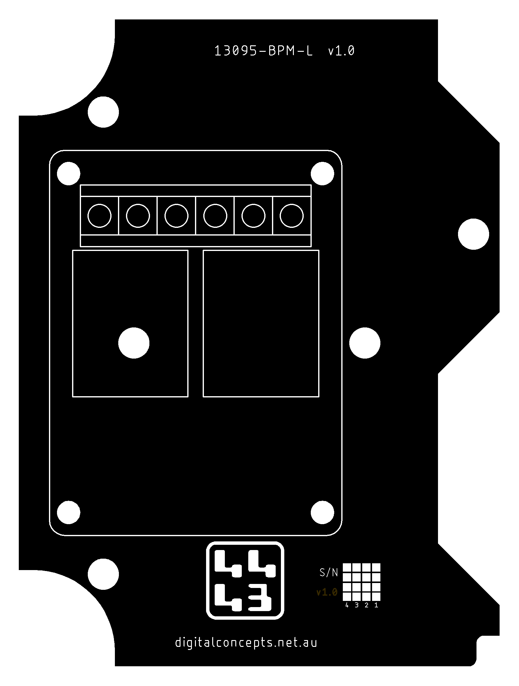
These are an iteration on the 13095-BP-L/R PCBs described above that include a fuse on the AC circuit, better separation of the high and low voltage elements and support for mechanical relays on both the active and neutral circuits. The landing pad provided for the fuse supports both panel mount universal car fuse and SMD ceramic type fuse holders.
.jpg)
The cut-outs at the bottom of the boards are designed to accommodate 12mm cable glands and the cables entering the enclosure.
| 13095-BPM-L | 13095-BPM-R |
|---|---|
|
|
|
|
13095-BPM-L Eagle CAD Files | [17 KB] |
|
|
13095-BPM-R Eagle CAD Files | [27 KB] |
|
|
13095-BPM-L CAM Files | [46 KB] |
|
|
13095-BPM-R CAM Files | [127 KB] |
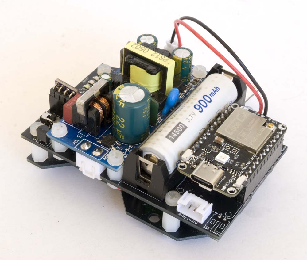
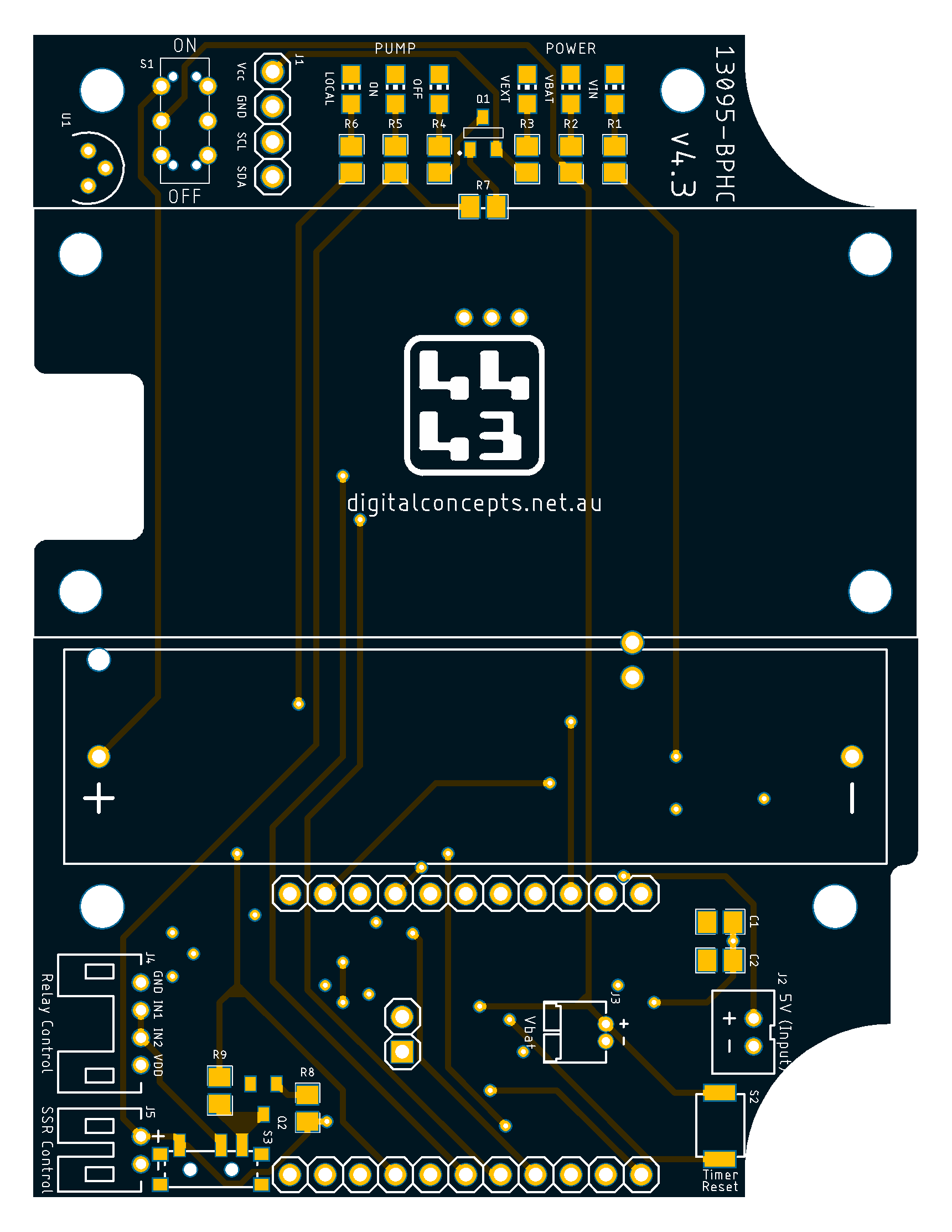
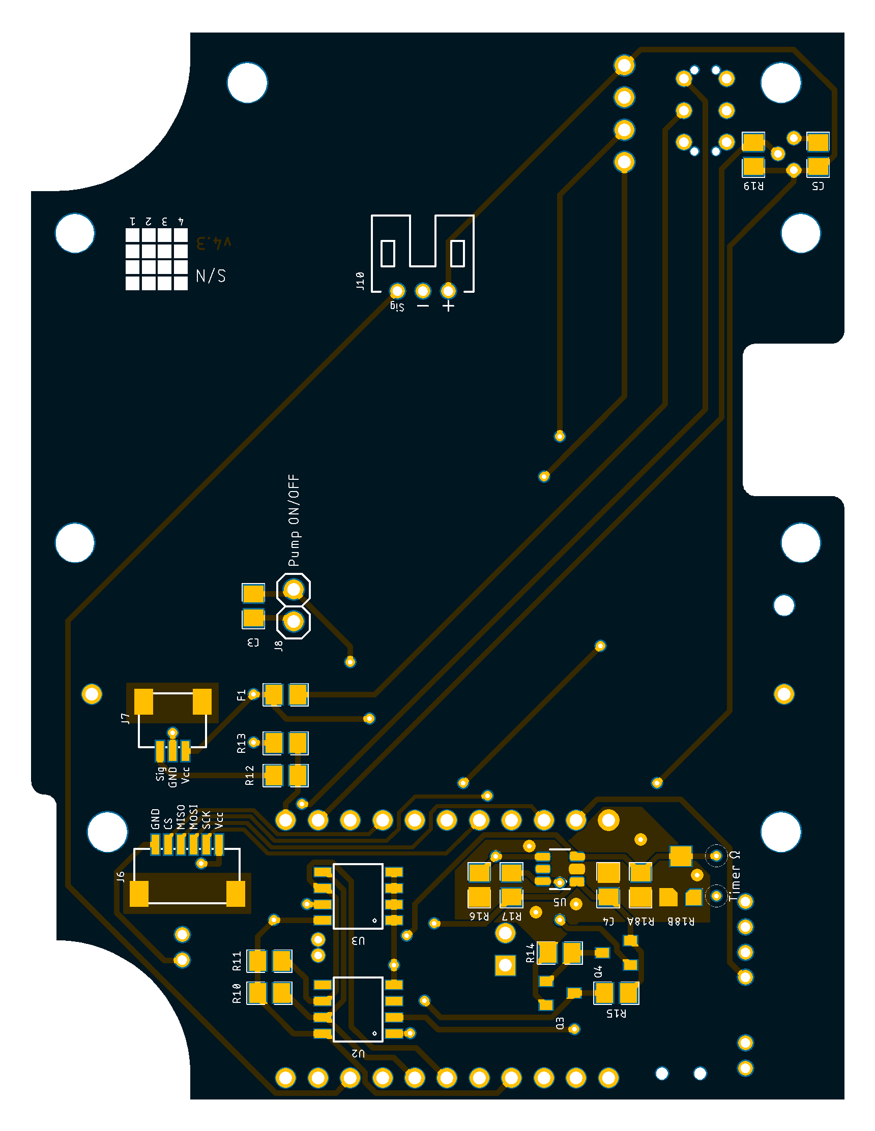
[13095-BPHC] Base Power board for Heltec CubeCell
This board is the processor support PCB designed to be used, in the 130 × 95 NHP enclosure, in conjunction with the two-part base board described above. The board is mounted on stand-offs, in the same way as my other 'board stack' configurations, in the right half of the enclosure, above the [13095-BP-R or 13095-BPM-R] right half board described above.
| Top | Bottom |
|---|---|
 |
 |
13095-BPHC PCB
|
|
13095-BPHC Eagle CAD Files | [114 KB] |
|
|
13095-BPHC CAM Files | [269 KB] |