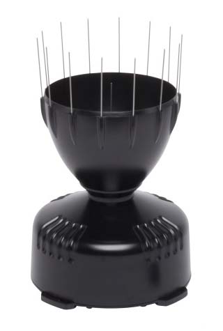
Davis 6466/6466M Rain Collector

Configuration
Hardware
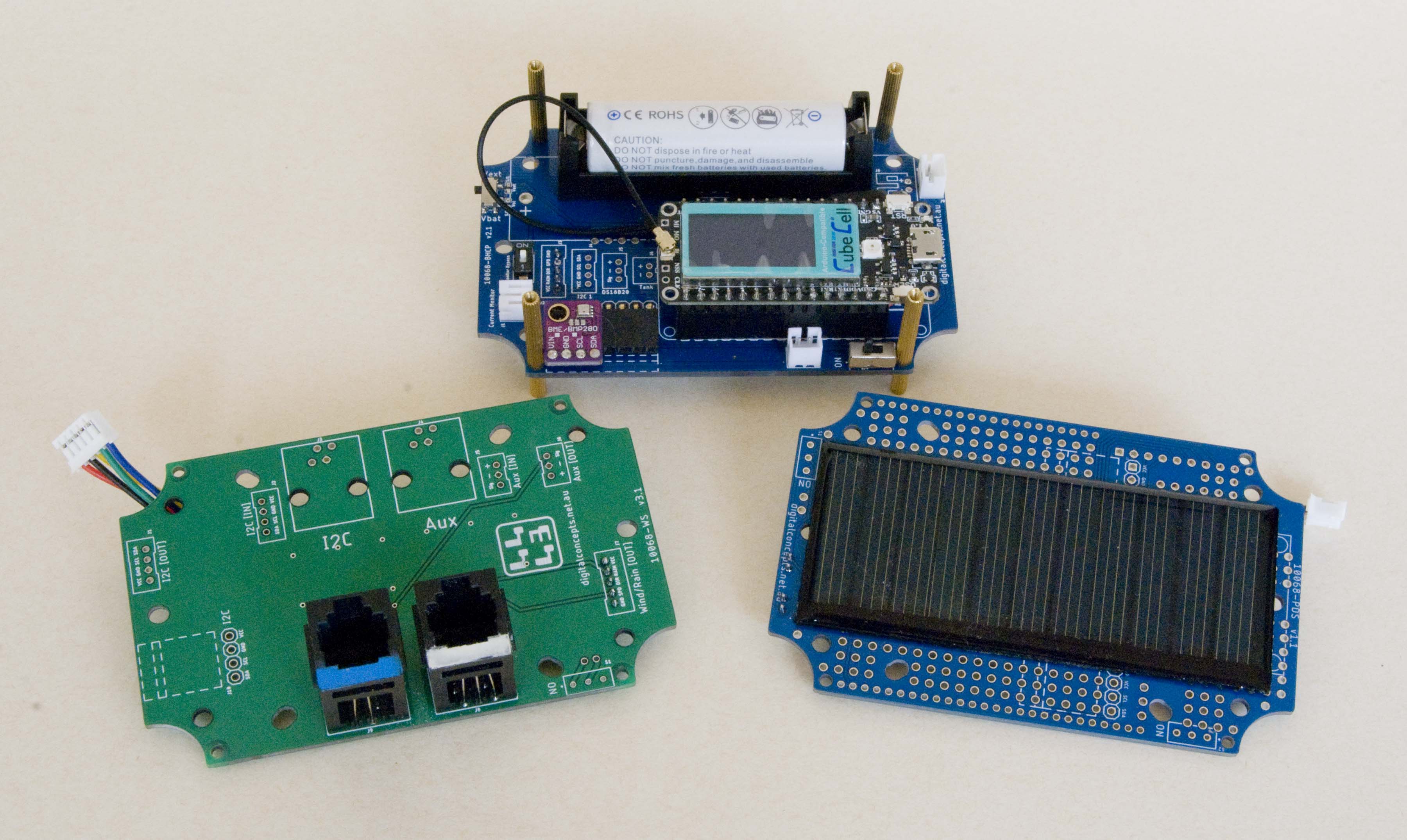
The rain collector, together with the anemometer, is currently configured in conjunction with the Heltec CubeCell Dev-Board Plus and the 10068-BHCP power management and 10068-WS weather station sensor interface PCBs.

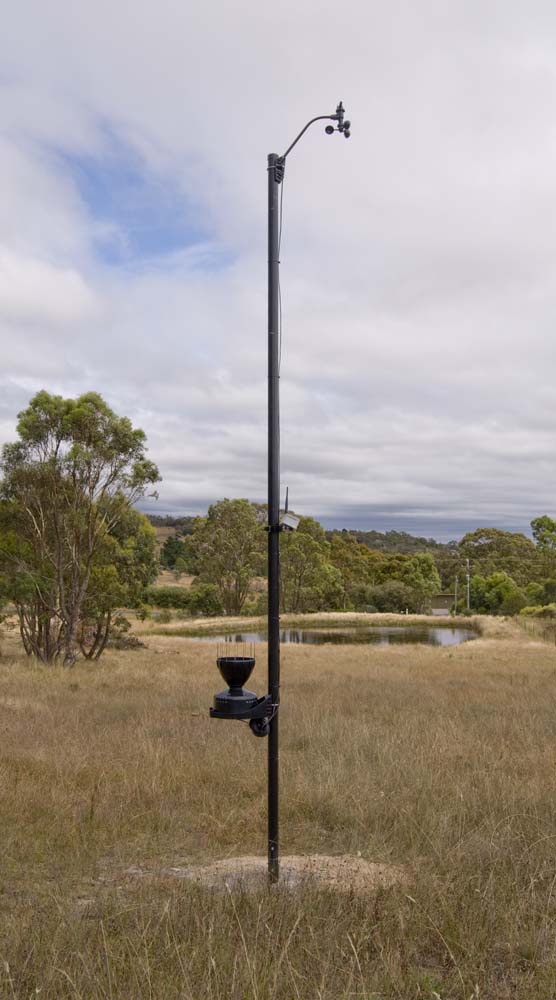
I'm not entirely comfortable with the current physical positioning of the rain collector, on the same pole as the anemometer, but closer to the ground. This does, more or less, seem to be the way the Davis weather station is intended to be set up (colocated, on a single pole), but it seems to me that the pole would interfere with the accurate measurement of precipitation. It may be that this has been considered, and that the relative sizes of the pole and the rain collector are such that the interference is negligible, but I think I might move the rain collector to its own pole in the future.
The 'Weather Station' Node is currently powered by a 900mAh 14500 (AA) Li-Ion battery, supported by an 80 x 35 5.5V 70mA solar panel. The CubeCell architecture includes onboard solar panel support and battery charge management hardware, so the only additional component required in the power circuit is a reverse current protection diode on the solar panel (refer to the 10068-BHCP hardware description for details).

10068-WS + 10068-BHCP + 10068-PDS
In this configuration, the battery has retained full charge throughout the summer months here in Australia, but has yet to be tested through an extended period of overcast weather. In some of my early experiments, I did notice that once batteries were depleted to a certain level, they were never subsequently fully recharged, with the result that, over time, they ultimately ran flat. It's not yet clear whether this is a general problem, common to all processor configurations, or a 'feature' of the CubeCell [Plus] battery management system.
I'll make an appropriate note here when I've completed more extensive tests on some of the other processor configurations.
Configuration
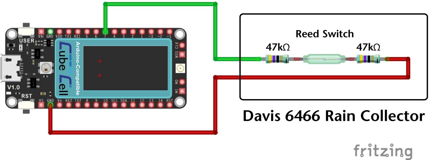
The essential operational mechanism and configuration of the present Davis 6466 Rain Collector—CubeCell Dev-Board Plus implementation is as illustrated below.
Davis Rain Collector Electrical Circuit
Pin Configuration
| CubeCell Plus | Davis 6466M |
|---|---|
| GND | GND |
| GPIO7 | Rain |
Note that the above is a simplified version of the circuit, intended to illustrate the internal configuration of the Davis sensor and it's logical connection to the CubeCell Dev-Board Plus. The 10068-WS board used in the present implementation incorporates additional line protection circuitry, which includes, for example, 10kΩ pull-up resistors on all digital lines (see 10068-WS Board Schematic).
 |
 |
Weather Station Node Board Stack
The rain collector is physically connected via an RJ11 socket on the 10068-WS board. The configurations of the rain collector cable and socket are illustrated below.
Davis Rain Collector Cable Configuration
Software
The script for collecting data from the rain collector is currently specific to the Heltec CubeCell Plus Dev-Board. I have tested the application of the general principles involved with other processors (Arduino Pro Mini, ESP-12 and ESP32), but the CubeCell Plus was the easiest module to program for this application so it became the first to actually be used.
System Functions
Sleep Mode
Sleep modes and their characteristics vary between the different processor families.
In the present application, there are two considerations in relation to sleeping the processor:
- Saving the state
- Minimising power usage of both the processor and peripherals.
For details on the implementation of sleep modes on the CubeCell platform, refer to the section on CubeCell software.
Interrupts
The measurement of both wind speed and rainfall employ processor interrupts, the mechanism for which differs slightly for the different processor families.
For details on the implementation of interrups on the CubeCell platform, refer to the section on CubeCell software.
EEPROM
Although the CubeCell architecture includes onboard memory that can be used to store data across processor restarts, I have used an external I2C EEPROM to be consistent with all of my other prototyping configurations. Note, however, that EEPROM usage on the CubeCell architecture requires a different library (AT24C32N.h) to that used by the other [Atmel ATmega328 and Espressif ESP-12 and ESP32] processors—refer to the section on CubeCell software for more detail.
The EEPROM is currently used to store a message sequence number (at location 0) and a rain counter (at location 512—see below).
Measuring Rainfall
Rainfall is measured in 0.2mm increments (the limit of the accuracy of the rain collector), via a tipping-bucket mechanism. Each time the bucket tips, a reed switch in the rain collector is closed, triggering an interrupt. An interrupt routine then increments a counter that is subsequently stored in EEPROM so that it will survive processor sleep or power off cycles.
The present application simply reports the current value of this counter each reporting period, and the receiving server converts this into a rainfall reading for the relevant reporting period. This reporting method largely obviates any need for reliable delivery of every packet. Each report, regardless of when it is received, effectively records the rainfall since 'time zero' and subtracting any reading from a subsequent one gives the rainfall for the relevant time interval. Wrapping of the counter will occur when it overflows, but this condition can be fairly simply managed by the receiving server application—biblical events notwithstanding, no single rain event on record would cause the counter to fully cycle.
There is also discussion in various quarters about 'debouncing' readings—the elimination of 'chatter' when reading the state of a toggled switch. In the pressent application, I have never observed chattering with the reed switch in the rain collector. Only once, in over 500,000 readings, have I ever recorded two triggers in a single 60 second interval, and that was during an exceptionally heavy (for my location) rain event, as would be expected. As such, I have not made any effort, in either hardware or software, to address the issue of debouncing.
Note: 29 Nov 2023 Contrary to my comments above, I believe I am seeing 'chatter' in my rainfall readings, so I will have to implement some form of debouncing, as many people have always suggested would be necessary. In what has clearly been steady, relatively light rainfall during the last 24 hours, reading every minute, I have noted 20 occurrences of 'multiple triggers' that could more reasonably be attributed to switch bouncing than a sudden increase in rainfall in just that 60 second period. More compelling, however, is the fact that I still have an old analog rain gauge and its recording over the same period was almost exactly what my electronic system would have been if I assume the multiple triggers were the result of switch bouncing.
Note: 11 Nov 2023 One problem that I have experienced, on two occasions now, is that something in the configuration is being impacted by 'near-by' lightening strikes. The problem manifests itself as a radical change in the rain counter—4280 one minute and 14820 the next, and 14908 one minute and 132 the next are the two changes I've observed, rather than the usual single digit increments. I originally thought that this must have been due to some sort of hit on the EEPROM, but the Sequence Number, which is also stored in EEPROM, never misses a beat—if the EEPROM was getting zapped, I would have expected the Sequence Number to also have been impacted.
I make this comment here because I am yet to determine the underlying cause of this problem.
Testing the Configuration
The following sketch, which runs on the CubeCell Dev-Board Plus, in conjunction with the 10068-BHCP power management and 100768-WS weather station sensor interface boards, incorporates the above and can be used to verify the CubeCell Dev-Board Plus/Davis 6466M rain collector configuration.
1 2 3 4 5 6 7 8 9 10 11 12 13 14 15 16 17 18 19 20 21 22 23 24 25 26 27 28 29 30 31 32 33 34 35 36 37 38 39 40 41 42 43 44 45 46 47 48 49 50 51 52 53 54 55 56 57 58 59 60 61 62 63 64 65 66 67 68 69 70 71 72 73 74 75 76 77 78 |
#include <Wire.h>// I2C Bus
#include <AT24C32N.h>// EEPROM management #include "CubeCellPlusPins.h"// CubeCell Plus pin definitions // Includes: //#define rainCollectorPinGPIO7 // Define the EEPROM parameters EEPROM_AT24C32NbhcpEEPROM; #define I2C_EEPROM_Address0x50 #define rainLocation512 #define rainBytes2 union EEPROMPayload { char payloadByte[2]; uint16_t counter; }; EEPROMPayload rainCounter; // Declare the global variables we'll use const uint16_t reportingPeriod = 10000;// In milliseconds, but keep it low while testing uint16_t rainCount = 0; void setup () { pinMode(Vext,OUTPUT); digitalWrite(Vext,LOW);// Turn on power to connected devices Serial.begin(115200); delay(200); Serial.println("[setup] Davis Rain Collector"); // Include the following function call to zero the rain counter //initialiseRainCount() // Set up the rain collector interrupt PINMODE_INPUT_PULLUP(rainCollectorPin); attachInterrupt(rainCollectorPin,incrementRainCount,FALLING); } void loop () { readRainCount(); delay(reportingPeriod); } void initialiseRainCount() { // This function is only called when we want to zero the rain counter rainCounter.counter = 0; Serial.println("[initialiseRainCount] Initialising rain counter..."); bhcpEEPROM.WriteBytes(rainLocation, rainBytes, rainCounter.payloadByte); } void incrementRainCount() { digitalWrite(Vext,LOW);// Make sure the external power supply is on delay(10);// Give everything a moment to settle down Wire.begin();// On with the show... bhcpEEPROM.RetrieveBytes(rainCounter.payloadByte, rainBytes, rainLocation, false); rainCounter.counter++; bhcpEEPROM.WriteBytes(rainLocation, rainBytes, rainCounter.payloadByte); Wire.end();// All done here } void readRainCount() { Serial.print("[readRainCount] Rain counter : "); digitalWrite(Vext,LOW);// Make sure the external power supply is on delay(10);// Give everything a moment to settle down Wire.begin();// On with the show... bhcpEEPROM.RetrieveBytes(rainCounter.payloadByte, rainBytes, rainLocation, false); Wire.end();// All done here Serial.println(rainCounter.counter); } |
Weather Station Application
The Weather Station application sketch can be downloaded by clicking on the following link. The EEPROMHandler and PacketHandler libraries can be downloaded from their respective downloads pages and the CubeCell Plus pin definition file from the CubeCell Platform page. I'll provide a complete description of what's going on at some point, but for the time being you'll need to look at the descriptions under each of the relevant sensors to see what's happening in each case.
The reader may also need to refer to the section on LoRa configuration.
Place the Weather Node sketch folder in the Arduino IDE root folder (Arduino). If running on a Heltec CubeCell Plus module, as is currently configured, this sketch also requires the latest version of the Heltec [CubeCell] hardware support libraries.

|
Weather Node [v2.3.2] | 31-Aug-2024 | [8 KB] |
Update: 30 Nov 2022 I only recently discovered that the above will probably not be entirely compatible with the version of the gateway software that is provided elsewhere on this site. The following is a version that uses the PacketHandler library. Once the PacketHandler and the relevant support files are installed, the following sketch should compile and run on the V1 & V2 Heltec WiFi LoRa 32 boards or the ESP32-WROOM-32 board, also described elsewhere on this site.

|
WiFi LoRa V2 Gateway [v2.2.2] | 17-Nov-2023 | [9 KB] |
Documentation

|
Davis 6466 Technical Specifications | [281 KB] |

|
Davis 6466[M] User Manual | [820 KB] |


