AJ-SR04M Ultrasonic Distance Sensor
Applications
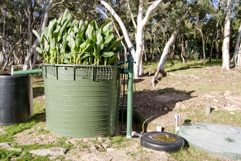
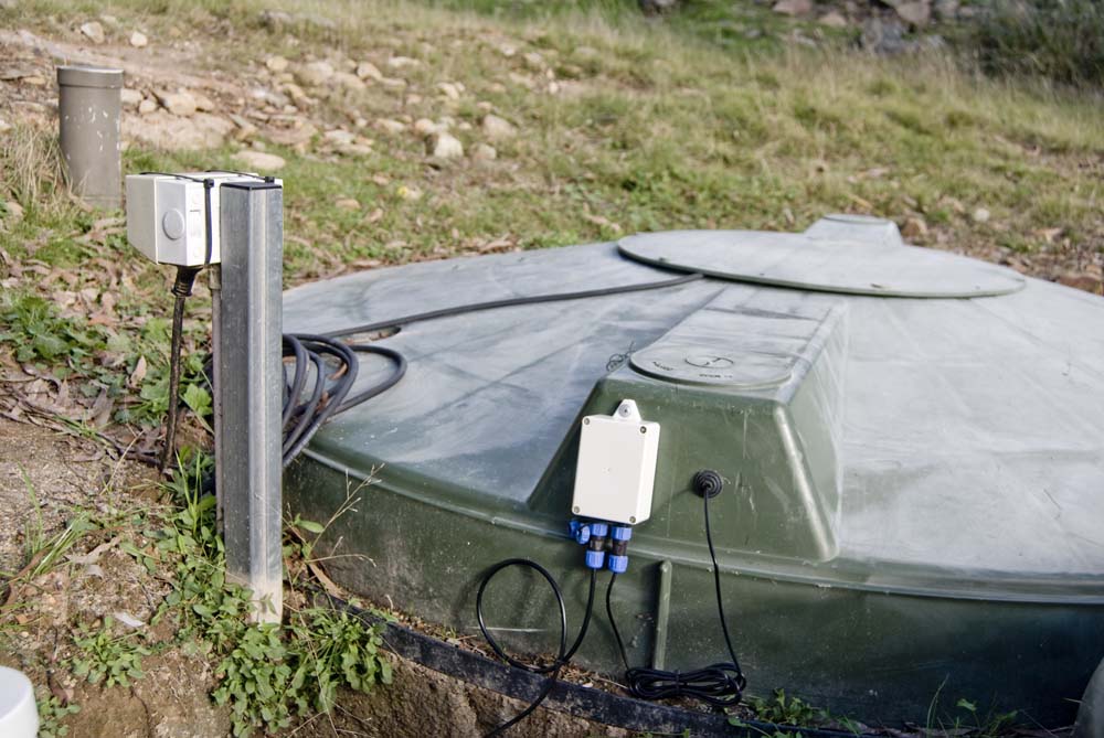
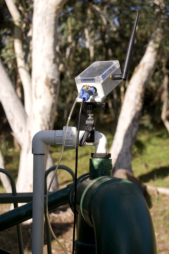
The ultrasonic distance measuring sensor is currently used to monitor effluent level in an aerated wastewater treatment system (AWTS). I chose this sensor, rather than the pressure sensor generally used in my water tanks, because, over time, the latter have shown a tendency to be impacted by the impurities, those present in bore water for example, and the AWTS is not exactly a 'clean' environment.
| AWTS | Ultrasonic Sensor Controller |
|---|---|
 |
 |
| Node | Sensor (Inside Tank) |
|---|---|
 |
 |
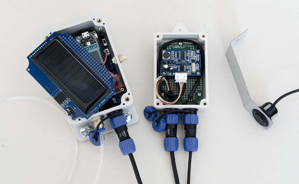
AWTS Ultrasonic Sensor Installation
As with most of the things I am doing, I have built on the efforts of others, starting with the AJ‑SR04M project described in Probots Blog. This sensor, or the interface card at least, seems to be generally referenced as being the same as the JSN-SR04T (V2?), although the board layout seems to be slightly different. In any case, I have never used anything other than the AJ‑SR04M module, so I can't comment on any differences that may exist.
I noted various discussions (like this one) about problems with these sensors and the need for special housings etc. to avoid spurious echoes and the like. In the present application, I found the best results when the sensor was installed entirely unimpeded, close to the top of my tank. The internals of my tank are a little complicated in that there are various plumbing elements descending into the tank. Nonetheless, provided the ultrasonic sensor was not in the immediate vicinity of any of this plumbing, and had an unobstructed 'view' of the water surface below, readings were consistent and reliable.
For reference, the sensor in the photo above (bottom right) is ~25cm from the wall of the tank, an Everhard Industries Model 87001 3000L Septic Tank (although my application is not as a traditional septic tank), which tapers in slightly towards the bottom but is otherwise a relatively flat surface, and ~150cm from the normal water surface. The plumbing to the right of the photo connects to a pump and the aeration system in the base of the tank and the sensor is sited so that its 'view' is not impacted by this hardware.
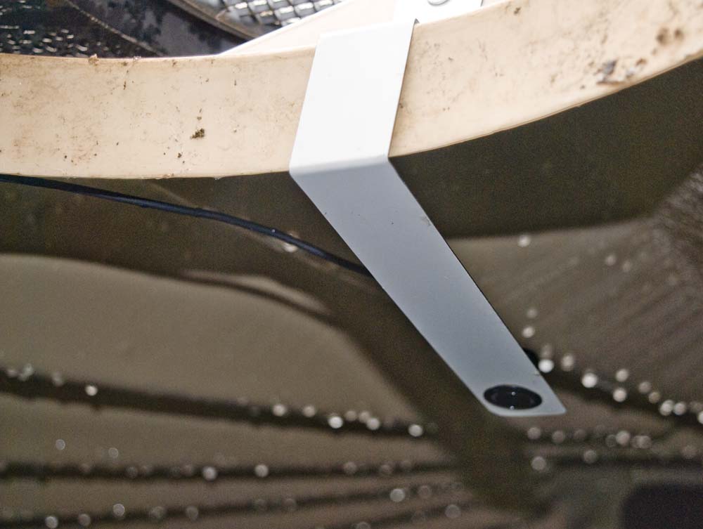
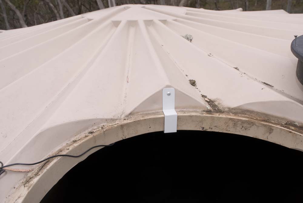
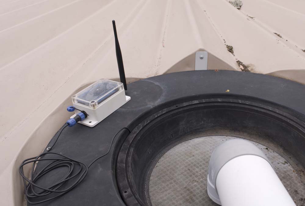
More recently, I have also started using a similar configuration to measure water levels in our rainwater tanks, primarily because it is much more economical (A$4 vs A$40+) than the pressure sensor that has been used to date. Unfortunately, mounting the ultrasonic sensor inside a tank is somewhat more fiddly than just dropping in a pressure sensor. The packaging for the electronics in this application is, however, more straightforward than for the AWTS application, with all but the sensor itself fitting neatly into a single enclosure.
| Sensor (Inside Tank) | Sensor Bracket Mount | Node Installation |
|---|---|---|
 |
 |
 |
Water Tank Ultrasonic Sensor Installation
Configuration
Hardware
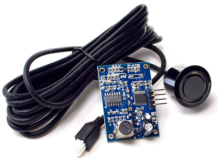
This device comprises a sensor that connects, via a 2.5 m, 2-wire cable and XH2.54 plug, to an interface board, which in turn presents a 4-pin header for connection to a microprocessor. While the interface board labels the power input pin as 5V, this sensor will operate on the 3.3V supplied by all of the processors that I use.
Controller Board
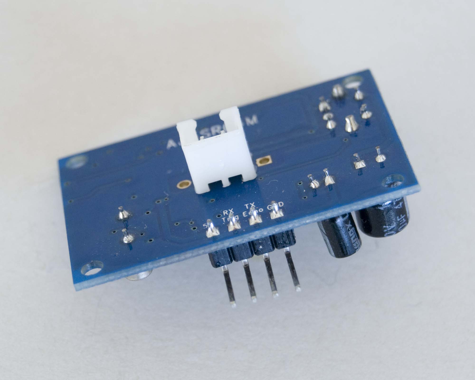
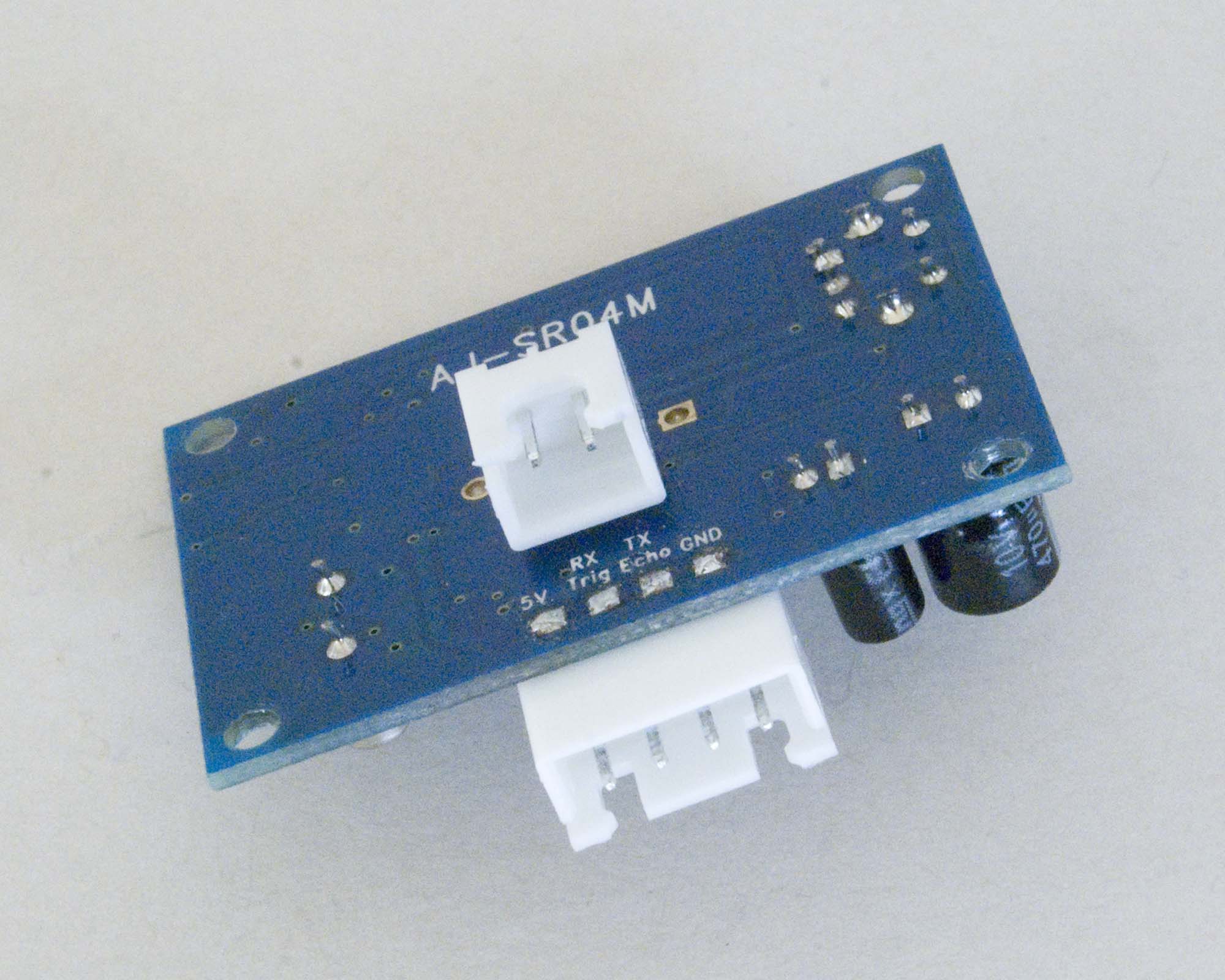
The configuration of the connectors on the sensor controller board, as supplied, is not particularly convenient for either of the present applications, with the XH2.54 sensor cable socket protruding vertically from the bottom of the board and, in the case of the AWTS application, the processor interface header horizontally from one edge.
To simplify the packaging of the interface board in the AWTS application, which needed to be relatively close to the sensor itself but then also needed to connect to a microcontroller that could be several metres further away, both of the existing connectors were replaced by right angle XH2.54 connectors. With this configuration, both cables effectively exit in the same direction from the interface board, simplifying their subsequent external connection.
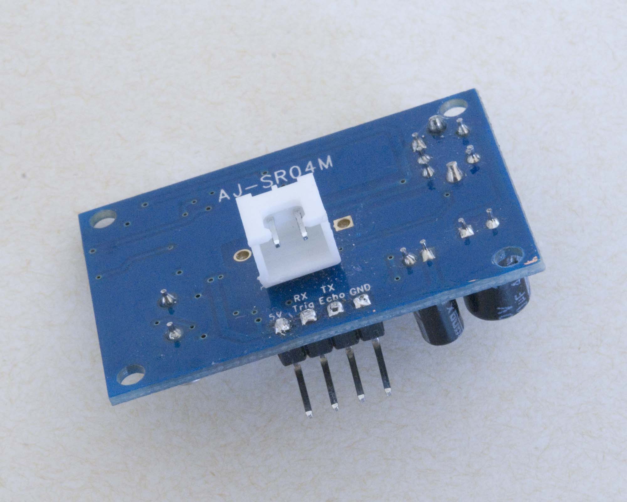
For the water tank application, only the 2P XH2.54 sensor connector needs to be modified.
Note: The pins on the 4P connector need to be trimmed flush with the board to avoid fouling with the sensor connector, and the 2P [sensor] connector needs to be mounted slightly proud of the PCB to accommodate the shrouded plug on the sensor cable.
| Original |
|---|
 |
| AWTS Node Modified | Water Tank Node Modified |
|---|---|
 |
 |
AJ-SR04M Interface Board Connectors
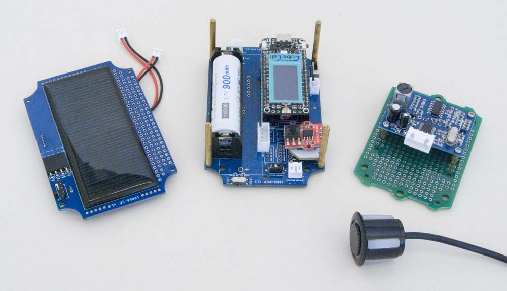
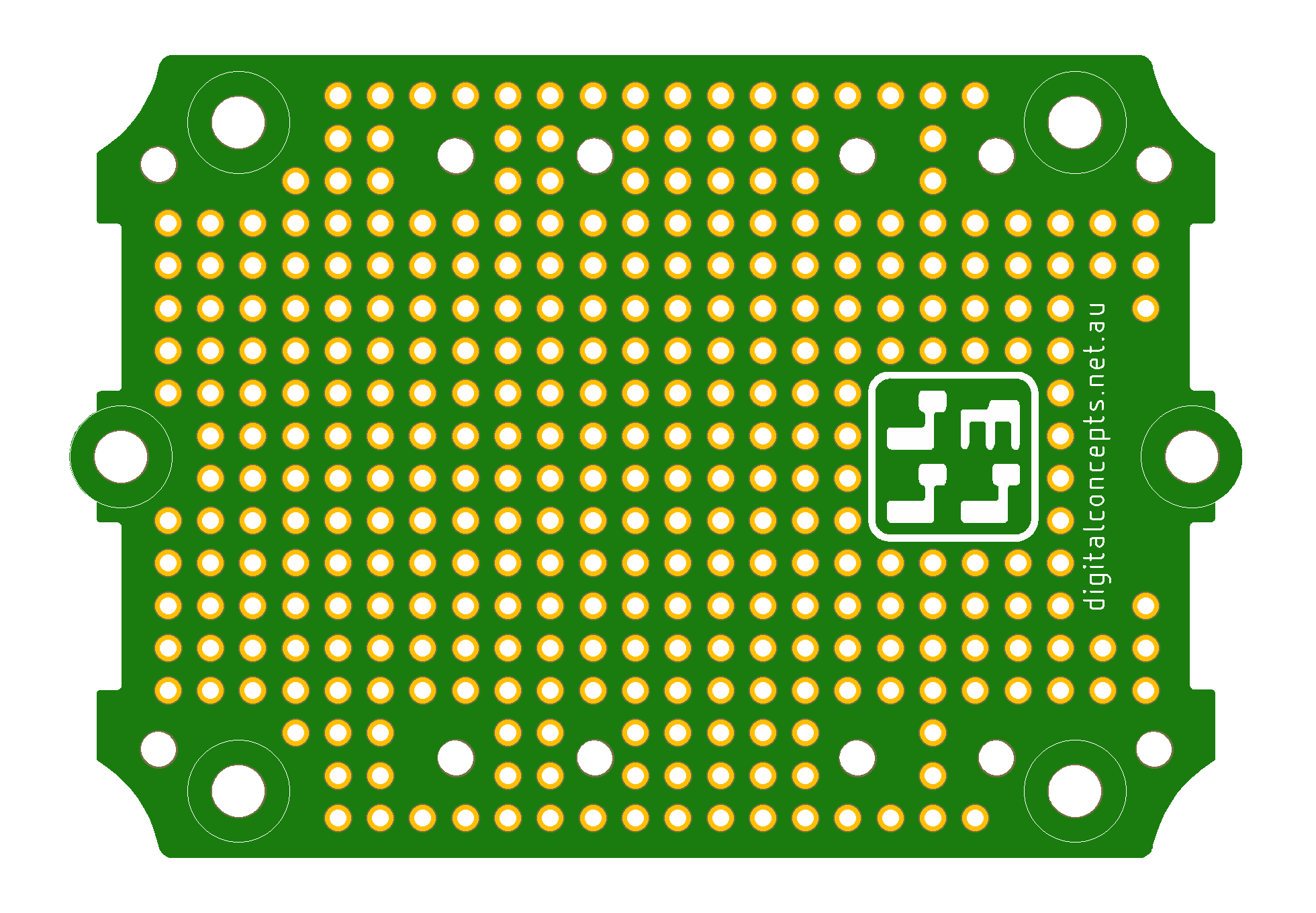
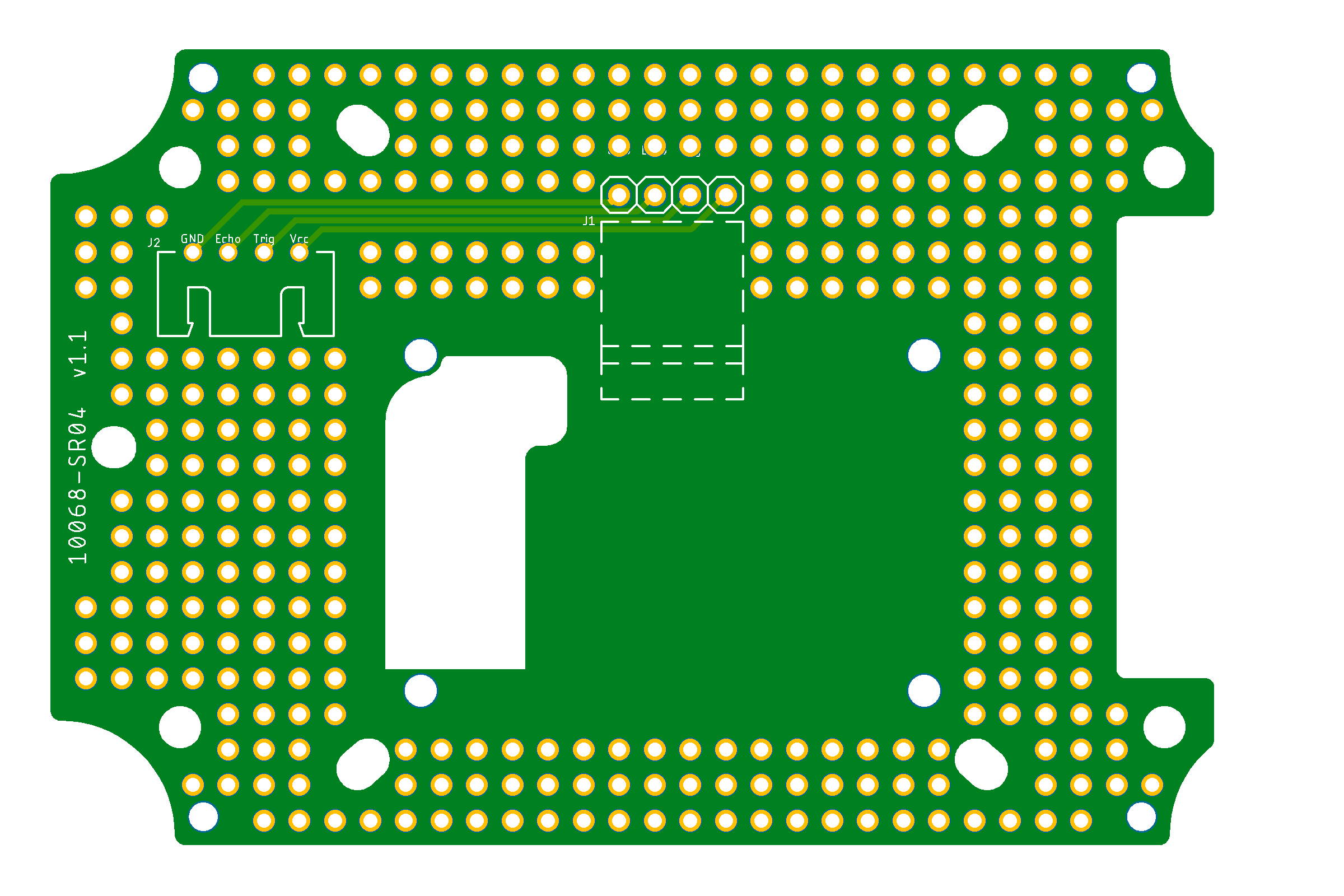
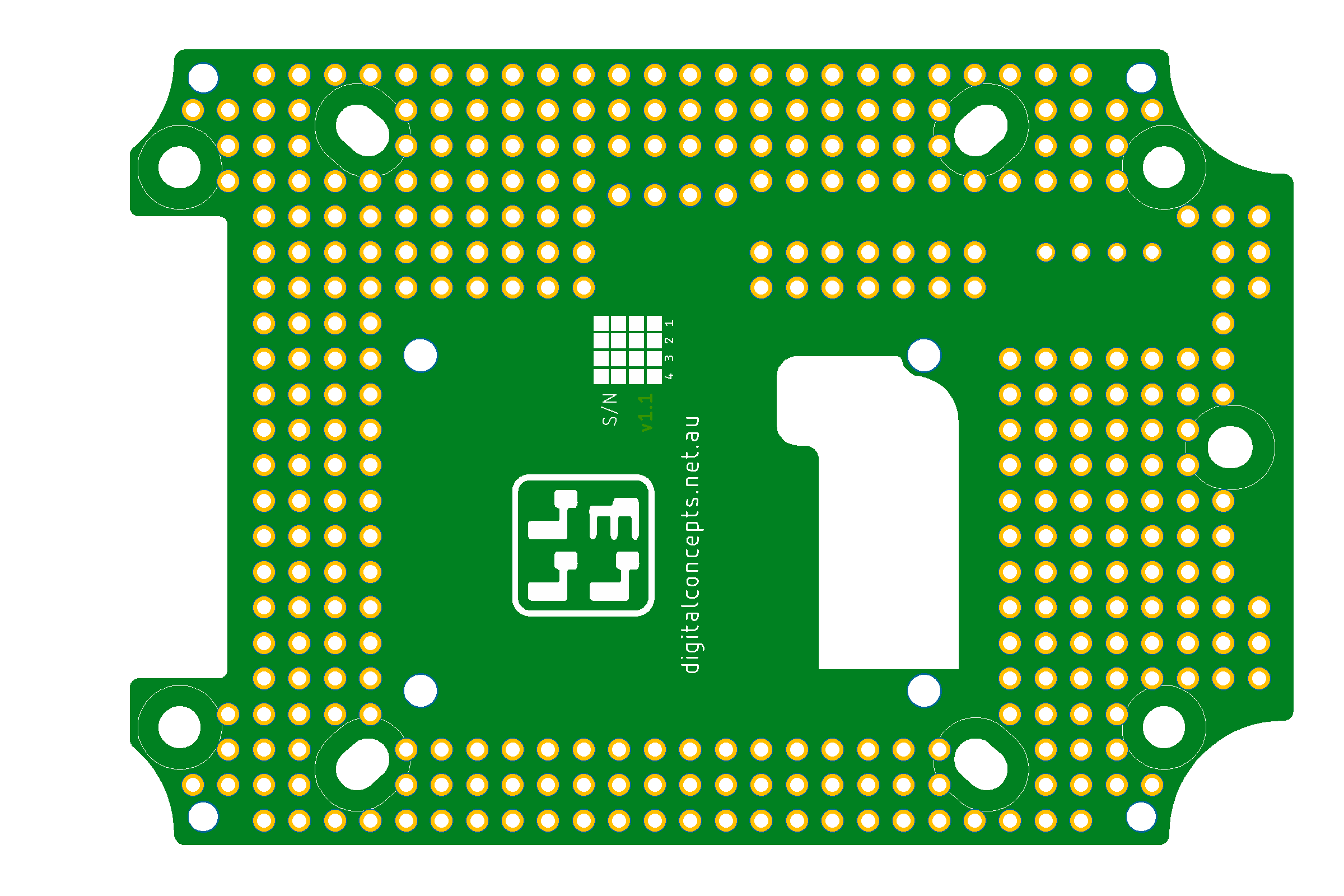
In order to mount the interface board neatly within one of my 'standard' enclosures, 85 × 58 cm for the AWTS application or 100 × 68 cm for the water tank application, I also created mounting boards that could be fixed into the enclosure to provide the necessary mounting points. Cut-outs on the boards are to accommodate external connectors that protrude into the enclosure and, in the case of the water tank application, the components of the controller board itself—see photos below.
| Top | Bottom |
|---|---|
 |
 |
8558-SC PCB

|
8558-SC Eagle CAD Files | [25 KB] |

|
8558-SC CAM Files | [54 KB] |
| Top | Bottom |
|---|---|
 |
 |
10068-SR04 PCB

|
10068-SR04 Eagle CAD Files | [69 KB] |

|
10068-SR04 CAM Files | [64 KB] |
Unused space on the boards is also populated with my standard array of pads to provide flexibility for any possible additional use.
For the AWTS application, the controller board is mounted on the 8558-SC support board using ?mm F-F M2 stand-offs within an 85 × 58 enclosure and the 10068-SP solar panel board is mounted on the 10068-BHCP processor board using ?mm F-F M2 stand-offs within a 100 × 68 enclosure.
AWTS Node Components
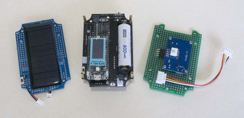
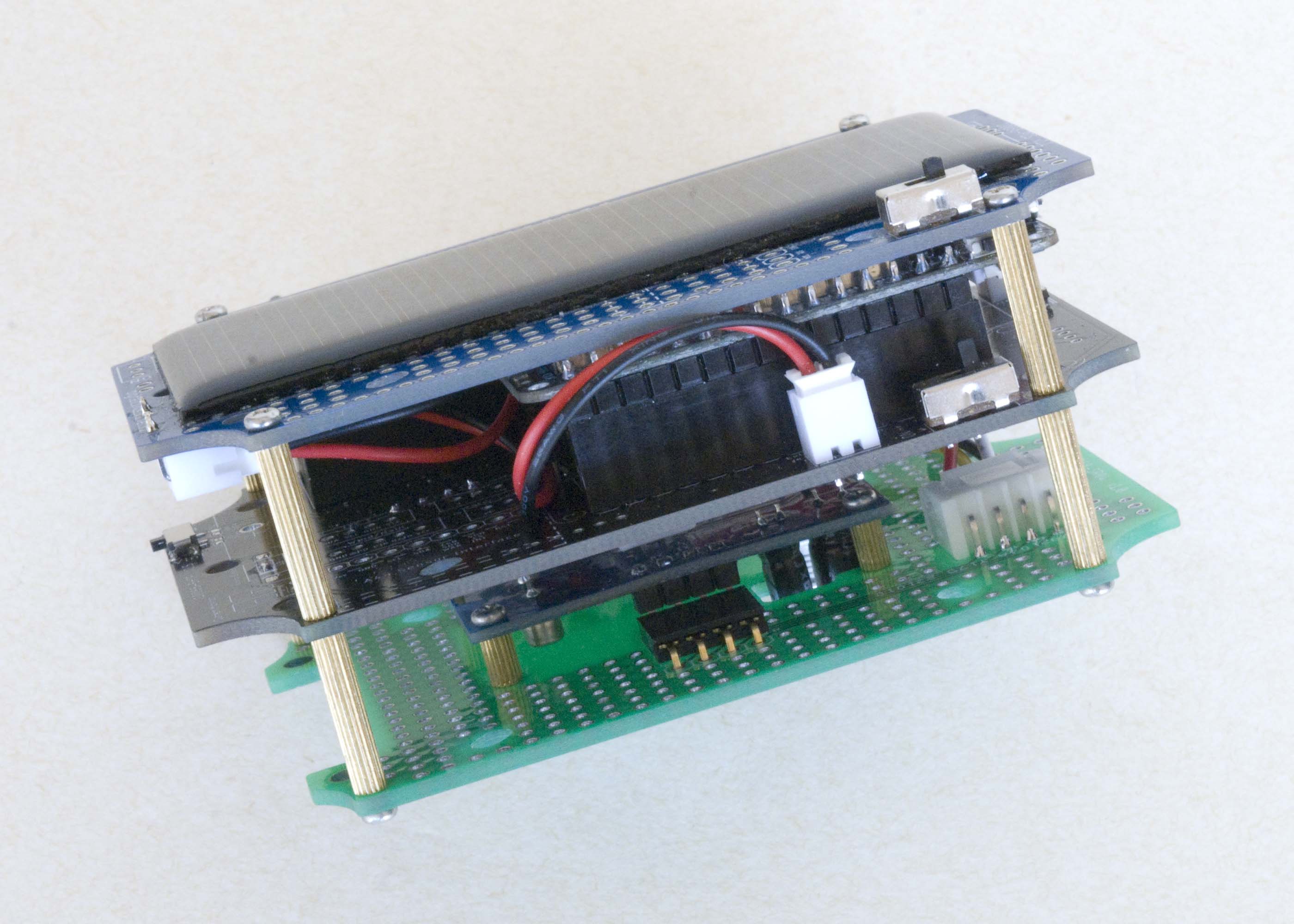
For the water tank application, the controller board is mounted on the 10068-SR04 support board using 5mm F-F M2 stand-offs. The 10068-BHCP processor board is also mounted on the 10068-SR04 support board, but using taller, 15mm M-F M2 stand-offs and the 10068-SP solar panel board is mounted on top of that, using 16mm F-F M2 stand-offs. The entire 'sandwich' thus [just] fits neatly into a single 100 × 68 × 50 enclosure.
Tank Node Components
Sensor
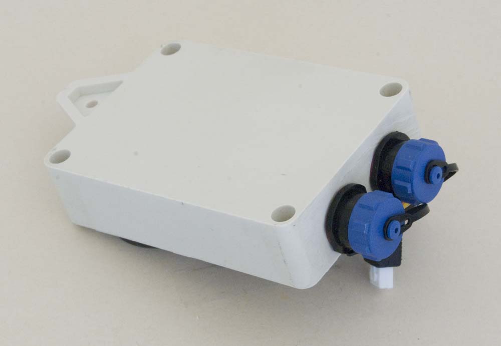
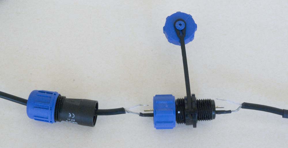
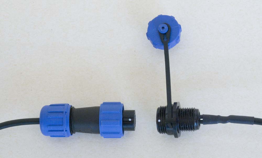
To provide the sensor connection, I cut the [coaxial] sensor cable and inserted one of the [SP11] Weipu waterproof connectors I use to connect to the enclosure internals. The 85×58 enclosure also had to be modified slightly by removal of one of the external mounting flanges and the 'bottom' [in the photo below] internal mounting post to accommodate the two connectors. The packaging is tight but the smaller the packaging the more flexibility I have in how and where a node can ultimately be mounted.
| Remove External Flange | Remove Internal Mounting Post |
|---|---|
 |
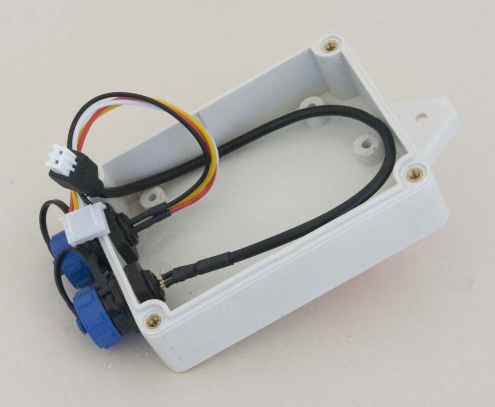 |
AWTS Controller Enclosure Modifications
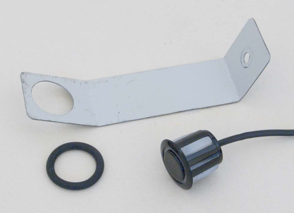
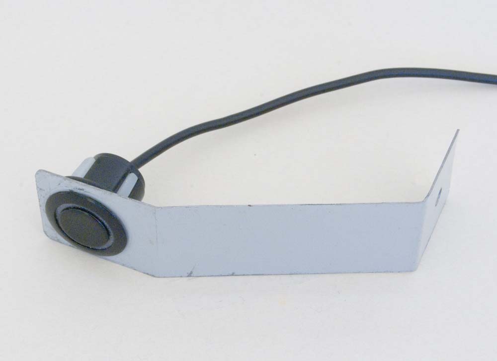
The AWTS sensor bracket was fabricated from a piece of COLORBOND® steel. The sensor mounting hole was a little larger than I would have liked for a snug fit, but that was the size I could cut with the step drill that I had so that was it. To hold it more firmly in place, I just used a snug-fitting O-ring around the back of the sensor.
| Components | Assembly |
|---|---|
 |
 |
AWTS Ultrasonic Sensor Mounting Bracket
The Water Tank sensor mounting bracket is similar, with folds required to hold the sensor horizontally inside the tank (see illustration above).
It doesn't really matter which pins are connected to which wires on the external connectors, but they obviously need to be configured the same way at each end and, if several similar Nodes are being configured, having them all the same keeps everything interchangeable.
| Polarity | Assembly |
|---|---|
 |
 |
Sensor Cable
Processor
Once again, the CubeCell Dev-Board Plus provided a convenient platform for this application, given that it has the capacity to concurrently support a wide range of sensors, including both the line air pressure and the present ultrasonic distance measuring sensors used in my AWTS application.
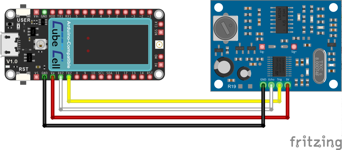
The current CubeCell Dev-Board Plus configuration is as illustrated below.
CubeCell Dev-Board Plus–JA-SR04M Electrical Circuit
Pin Configuration
| CubeCell Plus | AJ-SR04M |
|---|---|
| GND | GND |
| Ve | 5V |
| RX2 | Echo |
| TX2 | Trig |
Some people also recommend configuring a pull-up resistor (4k7–10kΩ) between the Echo pin and Vcc (5V/3.3V), but I've not experienced any problems to date without this.
The actual physical configuration of both applications, as currently implemented, is based on the 10068-BHCP base board and uses the physical GPS interface provided on that board, although the connection is provided through a 4P XH2.54 JST connector, on the top of the board for the AWTS application or the bottom for the water tank application, rather than the conventional header used by the GPS module (which would be located on the bottom of the board). The interface provided for a GPS module conveniently includes connections to the second set of CubeCell Plus UART (TX/RX) pins, which are used in the present configuration to communicate with the ultrasonic sensor interface board.
AWTS Node Assembly
| Stack | Assembly |
|---|---|
 |
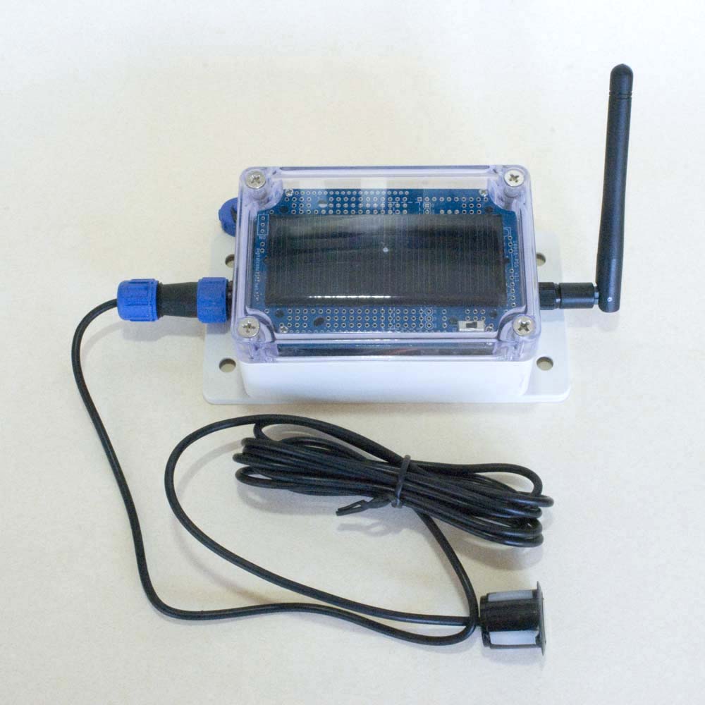 |
Water Tank Node
Software
While some people use the NewPing library, no special software library is actually required to use this sensor. As others have before me, my sketch simply raises the processor's 'trigger pin' for 10 microseconds and measures the delay before receiving a signal on the 'echo pin'.
It should also be noted that the sensor can be configured to work in several different modes (refer to the Probots Blog post for a detailed explanation of the different modes), generally through the addition of an appropriate resistor at location R19 on the interface board. In particular, some of these modes are low power modes, designed specifically for battery-powered applications. Since my processor boards, or the processors themselves, include the ability to power down peripherals in a low power operating mode, I have not bothered to investigate any of these options—I simply use the interface board in its default configuration.
Testing the Configuration
The following sketch, which runs on the CubeCell Dev-Board Plus in the configuration illustrated above, is based on that offered in several other posts. To assist with testing when a Serial Monitor is not available, the present version also generates output on the built-in display on the CubeCell Dev-Board Plus.
As with most of my sketches, processor pin definitions are included in the relevant <processor>Pins.h file, in the present case CubeCellPlusPins.h.
The distance travelled by the ultrasonic wave is calculated from the speed of sound and the elapsed time, using the following formula:
| Distance | = | Speed of Sound × Elapsed Time 2 |
taking 343 m/s (0.0343 cm/µs) as the speed of sound in air at 20 °C and noting that the distance to the 'measured surface' is half the round trip distance.
1 2 3 4 5 6 7 8 9 10 11 12 13 14 15 16 17 18 19 20 21 22 23 24 25 26 27 28 29 30 31 32 33 34 35 36 37 38 39 40 41 42 43 44 45 46 47 48 49 50 51 52 53 54 55 56 57 58 59 60 61 62 63 64 |
#include <HT_SH1107Wire.h>// CubeCell Plus display library
#include "CubeCellPlusPins.h"// CubeCell Plus pin definitions // Define the pins to be used #define echoPin ultraEcho// Refer to processor pin definition .h file #define trigPin ultraTrig// Refer to processor pin definition .h file // A couple more variables long elapsedTime;// Sound wave travel time int distance;// Distance measurement // The CubeCell Plus Display object SH1107Wire display(0x3c, 500000, SDA, SCL, GEOMETRY_128_64, GPIO10);// addr, freq, sda, scl, resolution, rst void setup () { pinMode(trigPin, OUTPUT);// Sets the trigPin as an OUTPUT pinMode(echoPin, INPUT);// Sets the echoPin as an INPUT pinMode(Vext,OUTPUT); digitalWrite(Vext,LOW);// Turn on power to connected devices Serial.begin(115200); delay(100); Serial.println("[setup] AJ-SR04M Ultrasonic Sensor Test"); display.init(); display.setFont(ArialMT_Plain_10); display.screenRotate(ANGLE_180_DEGREE); display.clear(); } void loop() { // Clear the trigPin condition digitalWrite(trigPin, LOW); delayMicroseconds(2); // Set the trigPin HIGH (ACTIVE) for 10 microseconds digitalWrite(trigPin, HIGH); delayMicroseconds(10); digitalWrite(trigPin, LOW); // Read the echoPin, returns the sound wave travel time in microseconds elapsedTime = pulseIn(echoPin, HIGH); // Calculate the distance distance = elapsedTime * 0.0343 / 2;// Speed of sound wave divided by 2 (out and back) // Give a bit of feedback Serial.print("Distance: "); Serial.print(distance); Serial.println(" cm"); display.clear(); display.setFont(ArialMT_Plain_10); display.drawString(10, 5, "Distance:"); display.setFont(ArialMT_Plain_16); String distanceString = String(distance); distanceString.concat(" cm"); display.drawString(10, 20, distanceString); display.display(); delay(500); } |
In practice, I have noticed a degree of variation in the measurement of elapsed time. This was not a real problem when simply monitoring the water level in a tank, but when it came to using the level to trigger events, it was more important to have a stable, and thus more predictable result. To this end, the present implementation takes 21 samples, at 100ms intervals, and selects the median value. This provided a more workable solution than simply using an average, as the average still varied noticeably with smaller sample sets. Taking only 11 samples was a little less stable—10-15% of samples are outliers, no matter how many are taken, but the median is more consistent in larger samples—and increasing the sample interval didn't improve the consistency of measurements.
Further, while the present arrangement, whereby all calculations are performed by the Node, and just the ultimate result reported, was fine in the original [AWTS] application, when it came to managing water storage tank details, it became apparent that it was better for the Node to simply report its 'observations', the relevant time delay, and let the ultimate recipient of this data do what was necessary to derive a useful result. I am yet to implement this change in the AWTS application (I will remove this note when the task is complete).
The Problem with Ultrasonic Sensors
There is one significant problem with ultrasonic sensors in this type of environment—condensation (water droplets) on the sensor surface. Unfortunately, when this occurs, the water droplets can reflect the ultrasonic signal yielding false readings and unreliable results.
This has never been a real problem in the case of the AWTS application. This may be because the tank is essentially buried and the temperature inside the tank does not vary greatly or it may be related to the fact that the tank never gets very full under normal conditions.
Condensation has shown to be more of a problem in the case of the rainwater tank, which is above ground and often over half full. In this case, the problem manifests itself as frequent, what amount to 100% full readings.
This is less of a problem when monitoring the level graphically, over an extended time period, as correct measurements seem to be made on a regular basis regardless. Fortunately, the sensor seems to make only two types of measurement—the correct one, and a 100% reading (when the signal reflects off a droplet on the surface of the sensor). As a result, the readings are not entirely useless, as a graph over time effectively fluctuates between these two values, the lower 'correct' reading and the upper erroneous 100% reading.
This does nonetheless make using these readings for critical applications, like pumping water between rainwater tanks based on water levels, a little impractical, seriously compromising one of my primary goals in this particular application.
Application Sketches
The application sketches and support files can be downloaded by following the links below. I'll provide a complete description of what's going on at some point, but for the time being you'll need to look at the descriptions under each of the relevant sensors to see what's happening in each case.
Place the EepromHandler and PacketHandler libraries in the Arduino/libraries folder.
Place the Langlo folder, containing the Langlo header files, in the Arduino/libraries folder. The Langlo folder, and the files it contains, can be renamed anything you like. These header files contain the required WiFi and MQTT configuration details and the pin configurations for the relevant processor dev-board.
Place the relevant Node sketch folder in the Arduino IDE root folder (Arduino). If running on a Heltec CubeCell Plus module, as is currently configured, this sketch also requires the latest version of the Heltec [CubeCell] hardware support libraries.

|
AWTS Node [v2.1.0] | 03-Apr-2024 | [7 KB] |

|
Water Tank Node [v1.2.0] | 03-Apr-2024 | [6 KB] |


