Solid State Relay Power Switch
|
|
Application
A Solid State Relay, itself controlled by a Heltec CubeCell configuration (9575-BPHC, 13095-BP-L & 13095-BP-R PCBs), is currently used to control water pumps, but could be used to switch ON/OFF any electrical device. Note that, in many jurisdictions, devices used to switch voltages as low as 25V AC must have been formally tested and certified.
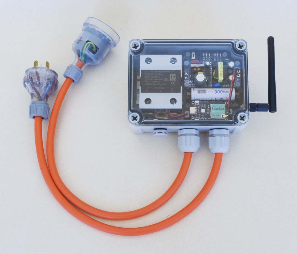
Power Switch Node
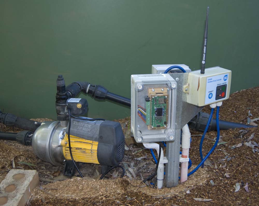
OpenSprinkler (left) and SmartWater pump controller (right)
I use [commercially sourced] pump controllers in two similar situations. I use one to control a pump that pumps water from a bore to a header tank. The pump is switched on when water in the tank drops below a certain level, and switched off when the tank is full. The second application is simply to pump water between tanks. In this case, the switch-on condition is similar, but as well as switching off when the destination tank is full, the pump is switched off if the water level in the source tank falls below a certain level.
Physically, the Pump Controller Nodes in both of these applications are identical. The difference between the two is managed entirely through software.
Configuration
The essential functions of the present SSR-based Power Switch Node are more integrated with those of the Gateway and MQTT broker than with other Nodes described on this site. All of the other Nodes simply report their status on a periodic basis. The Power Switch Node, however, acts on instructions from the MQTT broker, delivered via the Gateway Node. As such, it is important within this application for the broker to know whether or not there might be a communications problem that could impact the broker's view of the Power Switch status.
To this end, the original packet structure that was developed to support LoRa communications has been supplemented with a Reliable Packet Delivery Protocol (RPDP), which operates, between the Gateway and Power Switch Nodes, with status updates delivered to the MQTT broker as illustrated below.
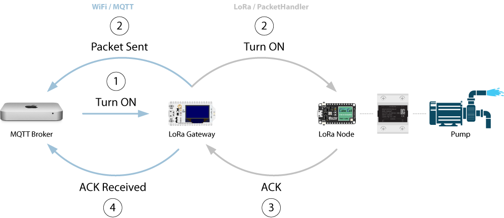
Power Switch Configuration
Hardware
Processor Configuration
The essential CubeCell Dev-Board configuration is as illustrated below. In addition to the CubeCell processor and SSR, it includes a local control button (and indicator LED) to manually control the relay and DS18B20 temperature sensor circuitry to monitor conditions within the enclosure (although both are optional), since SSRs have a reputation for generating heat under heavy load.
CubeCell Dev-Board–SSR Electrical Circuit
The Power Switch Node also includes several other additional, but optional components: an external [I2C] AT24C32 EEPROM for storage of configuration information (and a 4-pin I2C header for any other I2C sensor or device), an ACS712 current sensor and a TPL5010 watchdog timer (all omitted from the above illustration for simplicity—for full details, refer to the Schematic Diagram).
Pin Configuration
The following is a summary of the CubeCell pin configuration used in the present application. Note that, in order to monitor both the battery voltage and the ACS712 current sensor, a CubeCell Dev-Board V2, based on the ASR6502 processor (which has three ADCs, although only two are made available) is required. The original CubeCel Dev-Board, based on the ASR6501 processor, had only one ADC. The ACS712 current sensor can nonetheless be bypassed if not required.
| CubeCell | SSR | Local Control | DS18B20 | AT24C32 | ACS712 | TPL5010 |
|---|---|---|---|---|---|---|
| Vext | Vcc | Vcc | ||||
| Vdd | Vcc | Vdd | ||||
| RST | RST | |||||
| ADC | Viout | |||||
| GPIO0 | Done | |||||
| GPIO1 | Data | |||||
| GPIO2 | LED | |||||
| GPIO3 | Button | |||||
| GPIO5 | 3~6V + | |||||
| SDA | SDA | |||||
| SCL | SCL | |||||
| GND | 3~6V - | GND | GND | GND | GND | GND |
Enclosure
NHP N-Line 130 × 95 enclosure.
Photo(s) and any other relevant words...
Enclosure Layout
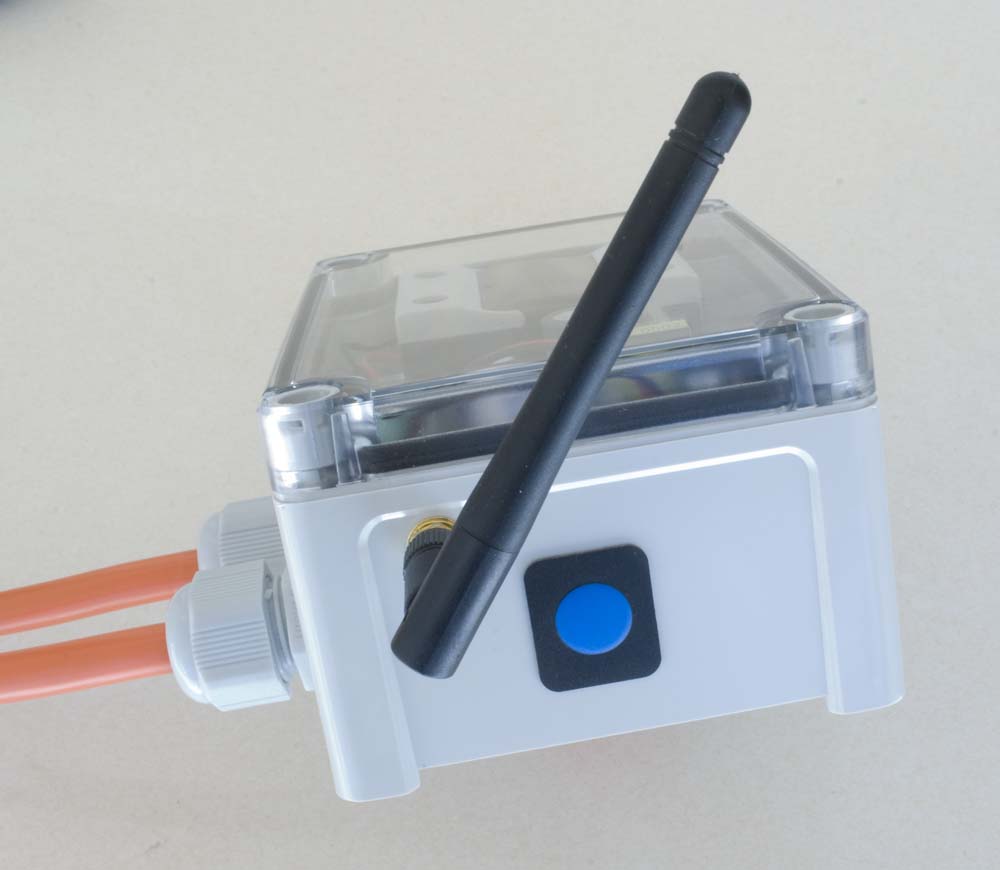
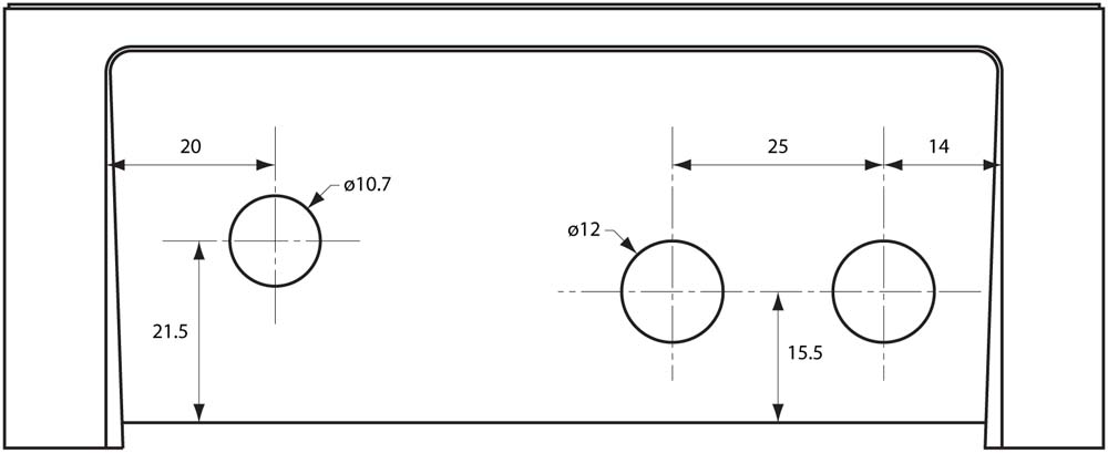
The packaging in the present enclosure is pretty tight. The external power cable glands need to be located as low and as close together as possible in the enclosure (allowing enough room to tighten the glands) to remain clear of other enclosure internals—the centres of the two 12mm holes are currently 25mm apart and as far to the right of the enclosure as was practical, matching the positions of the cut-outs in the 13095-BP-R PCB that accommodate the gland lock nuts inside the enclosure.
| Air Vent & Cable Glands | Antenna & Membrane Switch |
|---|---|
 |
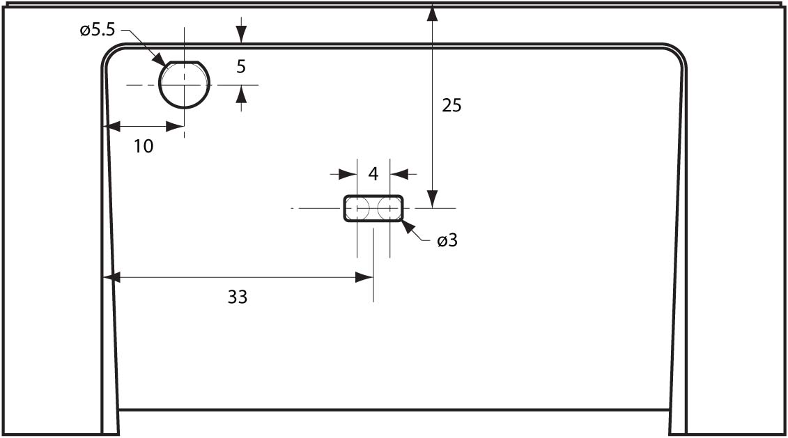 |
Enclosure External Connector Cut-Outs
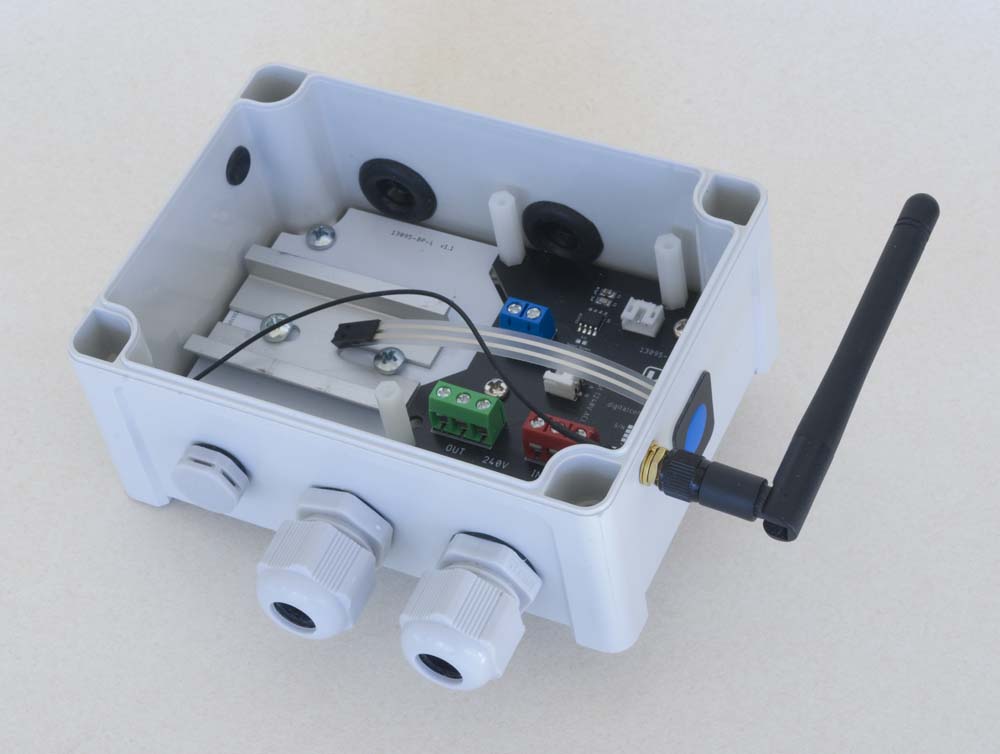
The 13095‑BP-R PCB must then be mounted on spacers (3mm) to provide clearance for pins that protrude through the bottom of the board as the enclosure mount points are flush with the bottom of the enclosure.
 |
.jpg) |
Enclosure Base Assembly (16mm gland configuration illustrated)
The 9575-BPHC PCB then needs to be located above the internal gland nuts—20mm M3 standoffs are currently used to this end. As a result, the hole for the antenna connection must then be located as high up and as tightly into the corner of the enclosure adjacent to the CubeCell Dev-Board as is possible so that the antenna pigtail clears the corner mounting screw and power supply JST connector.
The slot for the membrane switch cable, which can be formed by drilling two 3mm holes, 4mm apart, then filing out the space in between, needs to be located between the two boards, with the switch then mounted adjacent to the antenna.
Finally, the location of the air vent is not critical, although it can be conveniently accommodated beside the cable glands.
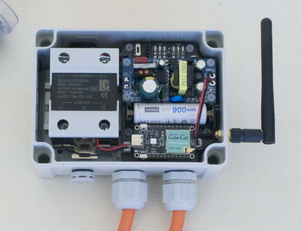
Power Switch Node Assembly (16mm cable glands)
PCBs
The base board for the 130 × 95 enclosure used in this application was fabricated in two parts (13095-BP-L & 13095-BP-R), primarily because it was too big to be managed by the free version of AutoCAD Eagle. As it turned out, this was not at all bad as there are no board-level electrical connections between the SSR, which is mounted on the left hand side of the enclosure, and the cable terminations and ACS712 current monitoring IC on the right hand side of the enclosure. This also enabled me to see what an aluminium PCB, one of the options provided by my fabricator JLCPCB, was like. Since this board is nothing more than a mounting platform for the SSR, I've no idea how it might perform as a PCB but, if nothing else, this was a relatively inexpensive way to fabricate a custom aluminium mounting plate.
| 13095-BP-L Top | 13095-BP-R Top |
|---|---|

|

|
13095-BP [v3.0] PCBs
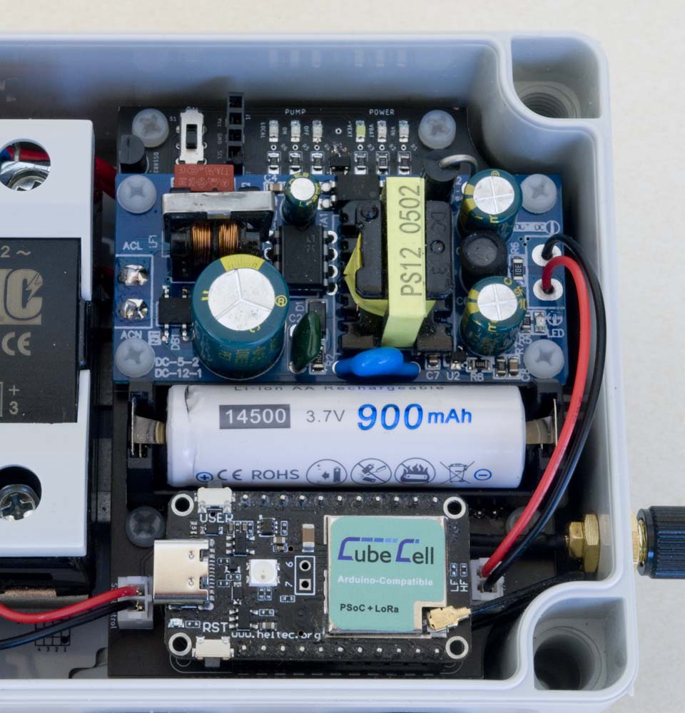
The processor, in this case a Heltec CubeCell Dev-Board V2, 5V DC power supply and backup battery are supported by a custom PCB (9575-BPHC) 'stack'-mounted above the right hand segment of the base board. The processor board is connected via JST connectors to the 240V AC source that provides input to the 5V DC power supply, the ACS712 current measurement IC and the control side of the SSR.
| Top | Bottom |
|---|---|
 |
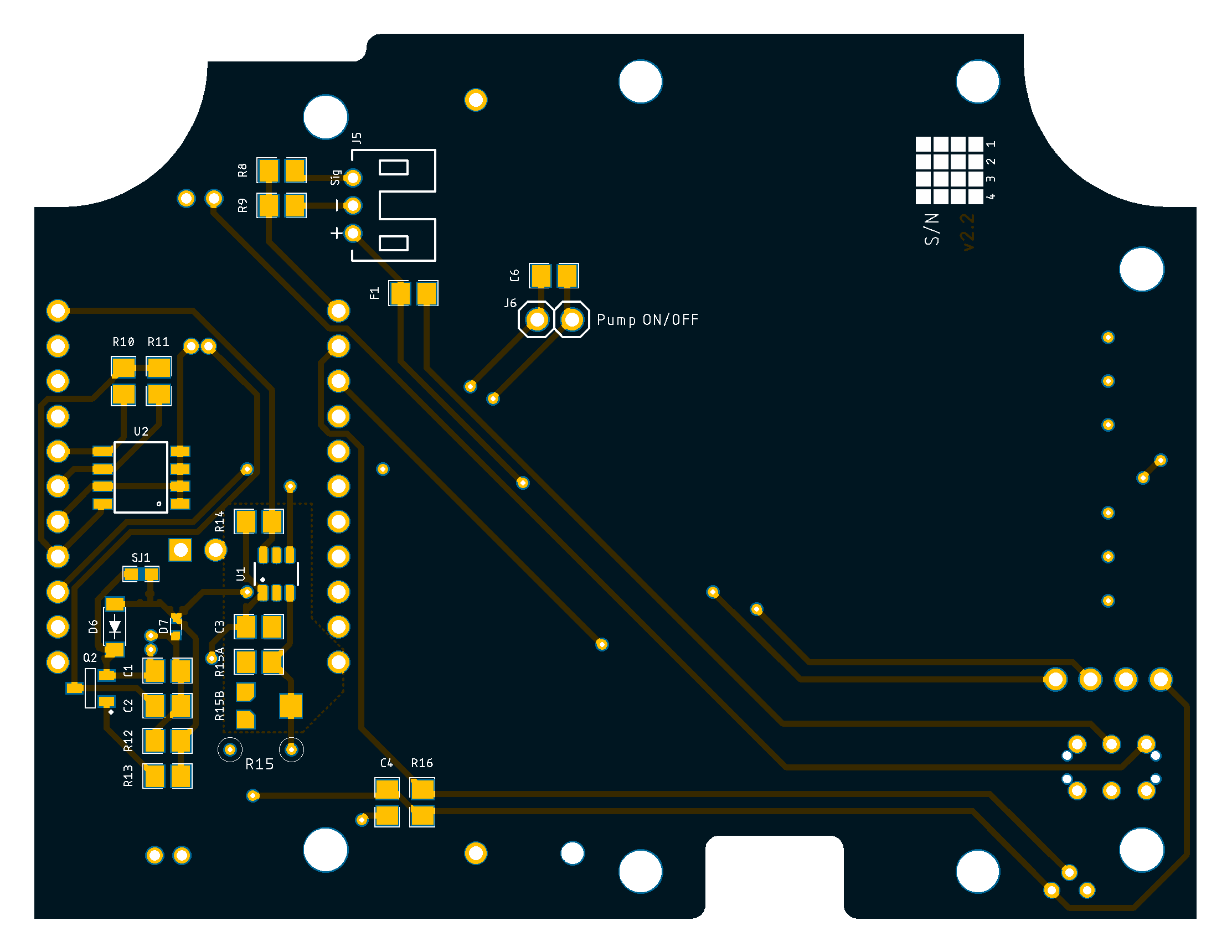 |
9575-BPHC [v2.1] PCB
SSR Characteristics
Zero-cross vs Random Turn-on
Much has been made of this, especially in relation to supporting inductive loads, which are claimed to require a Random Turn-on SSR. I must confess that, even after reading several papers on the subject, I do not understand why. The only specific negative comment I've read is that inductive loads do not always turn off when using a Zero-cross SSR but from all the descriptions I've read, the difference between Zero-cross and Random turn-on SSRs is the way they turn on— they both turn off in exactly the same way!
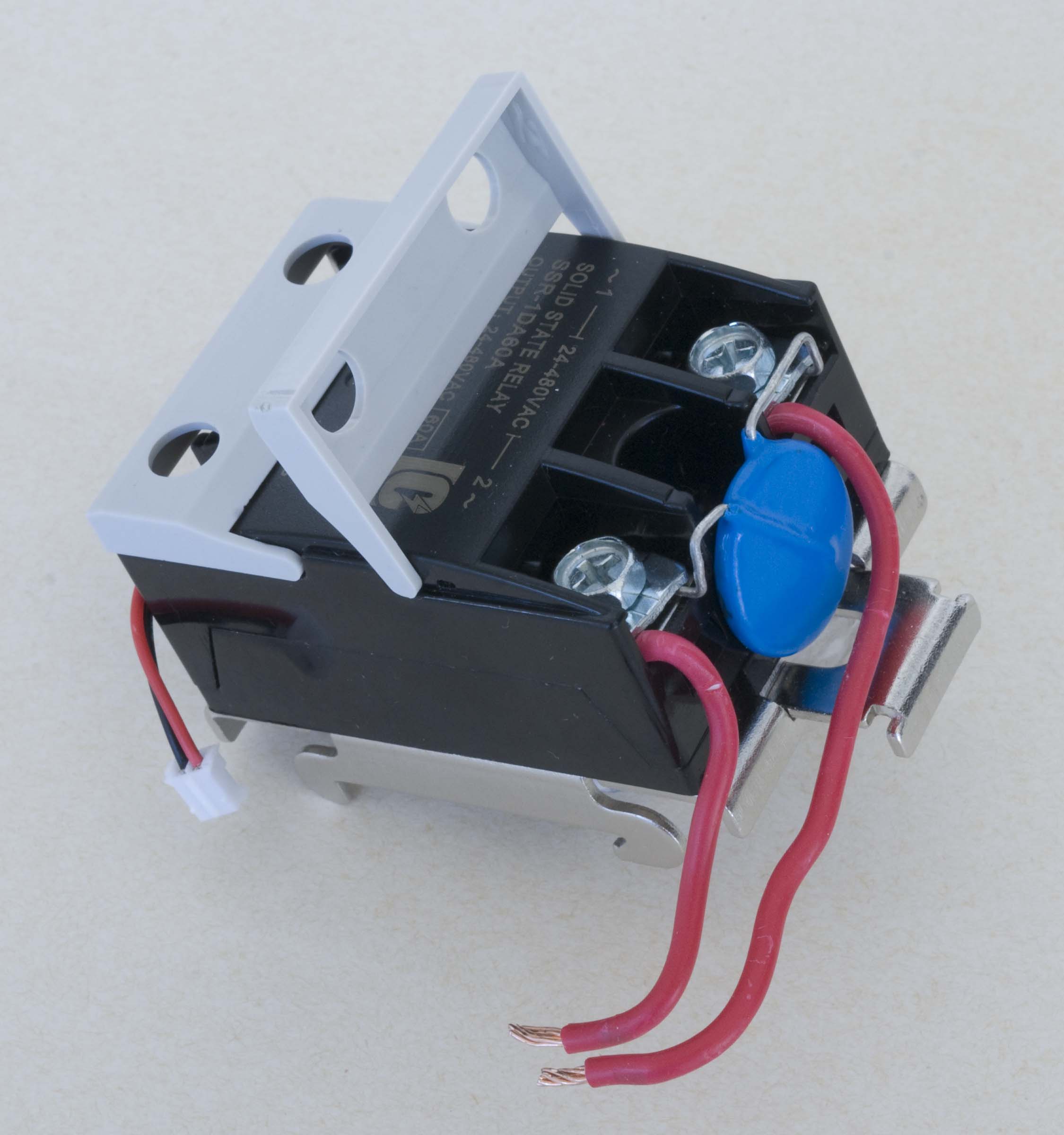
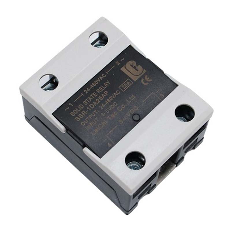
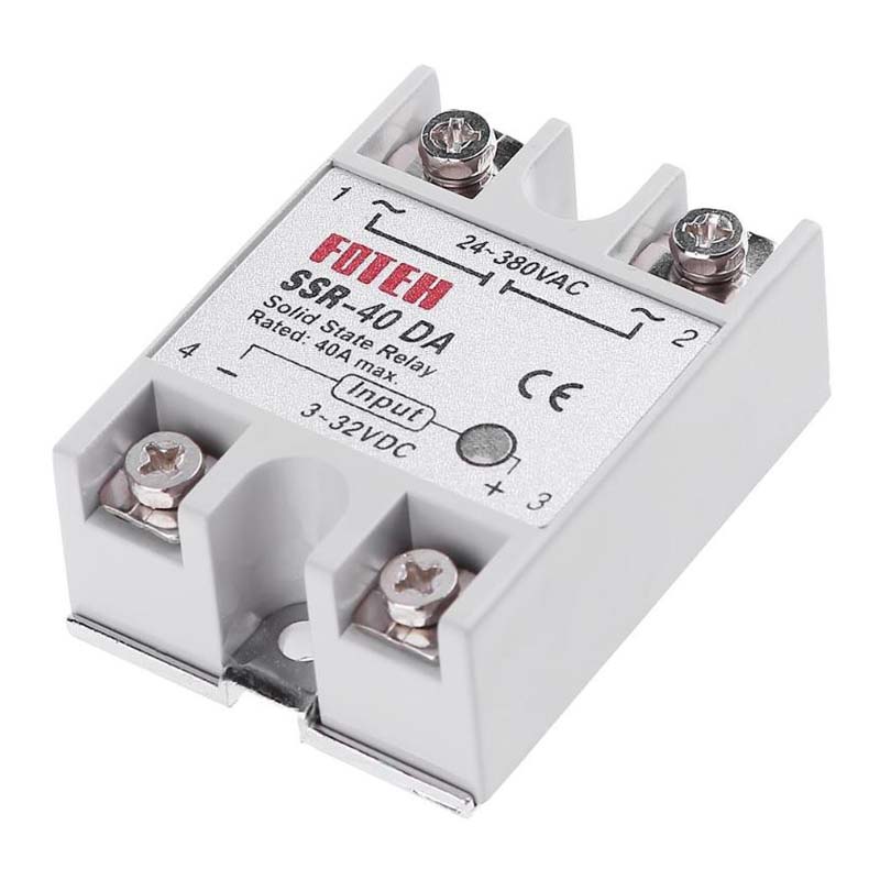
Nonetheless, I've used a Random turn-on SSR (at left in the image above and sourced here) in this application. Be aware, however, that most 'hockey puck' SSRs that I've encountered, like the most common FOTEK SSRs (at right in the image above) or copies thereof, are Zero-cross SSRs— you have to look carefully to find an SSR with Random turn-on switching.
The following notes on SSRs have been extracted from this Solid State Relay Guide by Phidgets.
The figure below, from the above-mentioned article, illustrates the difference in operation between Zero-cross and Random turn-on SSRs. The blue line represents the oscillating voltage of an AC load, and the shaded areas represent the sections when the relay is turned on, allowing current to pass through. Note that the Random turn-on SSR immediately opens when activated, while the Zero-cross turn-on SSR waits until the voltage crosses zero before opening.
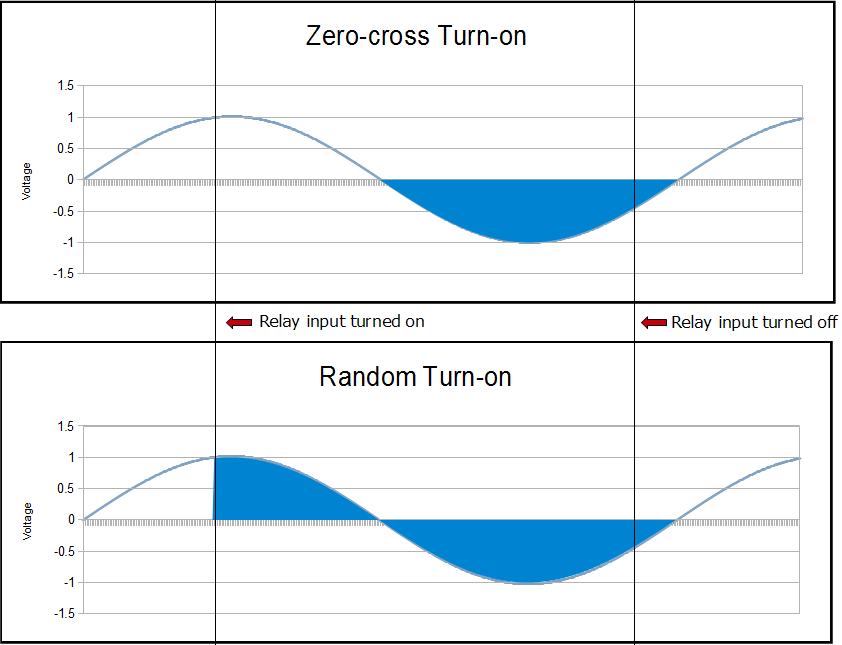
Zero-cross vs Random Turn-On
Zero-cross SSRs tend to create less electromagnetic 'noise' when they turn on and are often preferred for this reason, particularly for resistive loads. Apparently, however, inductive loads can cause problems with Zero-cross SSRs, but identifying which inductive loads will create problems is not straightforward so, as previously noted, most commentary simply recommends the use of a Random turn-on SSR in such cases.
With regard to determining the nature of a given load, it will usually be considered inductive if it is built around a large coil of wire—motors and transformers are typical examples. A load that is considered resistive may, however, also have loops of wire—for instance, hair dryers, toasters, incandescent bulbs use twisted wire elements to generate the heat. To be considered inductive, however, a load will generally have thousands of loops of wire—it's a matter of scale.
Load Classification
| Application | Load Type |
|---|---|
| Incandescent Light Bulbs | Resistive |
| Fluorescent Light Fixtures | May be Inductive (magnetic ballast) or Resistive (electronic ballast) |
| Motors | Inductive |
| Transformers | Inductive |
| Heaters | Resistive |
| Computer / Electronics | Resistive |
| AC/DC power supplies (brick heavy type) |
Inductive |
| AC/DC Power supplies (lightweight switchers) |
Resistive |
Current Rating
In order to size an SSR, we need to know the current drawn by our load when it is first turned on. Many loads demand a surge or inrush of current when first connected, placing a degree of stress on the electronics inside the SSR. In the same way that it takes a lot of force to move a heavy object from rest, it initially takes a lot of current to power up a fan or incandescent bulb. Given the difficulty in measuring surge current, a simple multiplier, applied to the normal operating current, is usually employed to size an SSR for a given application.
Load Current Multipliers
| Application | Multiplier |
|---|---|
| Incandescent Light Bulbs | 6× |
| Motors | 6× |
| LEDs | 1× |
| Complex Electronics (Motor Controllers etc.) | 6× |
| Fluorescent Light Fixtures (AC only) | 10× |
| Transformers | 20× |
| Heaters | 1× |
More generally then:
For a resistive load—resistance furnace, incandescent lamp, oven, heating rod, electric water heater:
SSR Current Rating = 3 × working current of load
For an inductive load—motor, fan, transformer, pump, air conditioner and other loads with inductors:
SSR Current Rating = 6 × working current of load
For a capacitive load—compensating capacitors, batteries and other loads with capacitors:
SSR Current Rating = 10 × working current of load
Temperature
The current drawn by a load will also determine how hot an SSR will be when in use. In general, the operating environment should be kept below 80°C and an appropriately sized heat sink used if required to achieve this. As a rule of thumb, however, loads that draw less than ~5 amp under normal operating conditions will not require a heat sink.
Comment on conditions actually observed in current application.
SSR Protection
Some commentary suggests that a Metal Oxide Varistor (MOV) should be installed across the [AC] load terminals of the SSR to absorb high voltage spikes. High voltage spikes are generally caused by inductive loads when they are turned off.
SSR MOV Configuration
In the present case, a Jaycar RN3404 MOV 275VAC 6500A has been configured across the AC terminals of the SSR. Regardless of whether or not a MOV is installed, it is also recommended that a fast fuse (70% of rated SSR) be used to protect the SSR from any load short circuit. To this end, the present circuit also includes an optional panel mount fuse holder.
Photo of installed fuse
Power Supply Fuse
Local vs Remote Operation
While the Power Switch Node is generally designed to be operated remotely, via a combination of the Node-RED dashboard, MQTT and LoRa, it can also be operated manually via a membrane switch button located on the Node enclosure. This button can be used to switch from the default, Remote Control Mode, to Local Control Mode and back again and, while in Local Control Mode, to control Node operation.
Local Control Button
To switch the Node into Local Control Mode, the button must be pressed and held for at least 3 seconds. When the Node has transitioned to Local Control Mode, the blue 'Local' LED will light on the Node status panel and the power can be toggled ON or OFF by briefly pressing the control button. In Local Control Mode, remote control is disabled.
To return to Remote Control Mode, the control button must again be pressed and held for at least 3 seconds. When the Node has transitioned back to Remote Control Mode, the blue 'Local' LED on the Node status panel will go out.
Power Supply
There are two power requirements with the Power Switch Node—the power supply to be switched and power for the local processor. Given that the Node will not be of much use if the switched supply is not available, it was a logical choice to also use this, with an appropriate converter—in the present case, an 85-260V AC to 5V DC switch mode power supply—as the primary power source for the controlling processor, rather than relying on a battery and solar panel like most of our other applications.
MCU Power Supply
In the present case, battery power is provided merely as a backup for the processor, so that it can continue to report on the status of the Node, for at least the life of the battery, in the event of power failure—the CubeCell's onboard battery management circuitry is used to maintain battery charge under normal operational conditions.
Temperature Sensor [DS18B20]
I generally include some type of temperature sensor in all of my Nodes. In the present case, this seemed particularly relevant as SSRs have a reputation for overheating. While not actually fixed to the bottom of the SSR, it is located immediately adjacent to the SSR on the 9575-BPHC PCB. It is therefore recognised that temperature measurements will lag behind and be lower than the actual temperature of the SSR and this fact needs to be taken into account in setting the threshold for any temperature warnings.
EEPROM [AT24C32]
While the ASR6502 MCU used on the CubeCell V2 Dev-Board includes its own, on-board EEPROM, an external EEPROM has been configured to provide consistency with other processor configurations used in this project. There are no specific Power Switch Node parameters stored in EEPROM at this point, just the Node identification data that is stored in all Node configurations. Refer to the description of the EEPROMHandler for details of the parameters that are stored in and functions used to access the EEPROM.
Current Sensor [ACS712]
The ACS712 current sensor circuitry is configured on the 13095-BP-R PCB, on the active lead to the SSR. A connection is then provided to the 9575‑BPHC processor PCB via a [JST] PH2.0 fly lead.
I don't know exactly how I'm going to use this yet. I included it because I saw the possibility that we might want to verify that the pump was actually running (i.e. drawing current) at some point. Nonetheless, using that information, however we might, will ultimately be a software consideration.
Watchdog Timer [TPL5010]
Although I have been testing the application of a range of processors in various IoT Node applications, most sensor Nodes have ultimately been based on the CubeCell ASR6502 platform. Whether it's to do with this specific hardware platform, or some element of the software involved, or just a fact of life when working with these sorts of processors, the Nodes occasionally hang. The AWTS Node has never hung, but the Weather Station Node seems to stop transmitting once or twice a year. With the Power Switch Node, there was a tendency for the processor to freeze more frequently, although in this case I believe that the main problem was with my software—I had not worked through the various elements of the control protocol thoroughly enough to eliminate all potential sources of deadlock. In this latter case, things have improved with refinements in the Node software, but all of these problems have been successfully managed by simply resetting the processor, the very task that is the function of a watchdog timer.
There are a couple of reasons for configuring an external watchdog timer. The first is that I have had difficulty getting internal watchdog timers, where they have been provided, to work satisfactorily. The second is the varied commentary on the subject that suggests that a watchdog timer that is internal to a processor cannot provide complete protection against a fault in the same processor.
The TPL5010 watchdog timer works in much the same way as the TPL5111 timer described elsewhere on this site. The resistor settings and timings for the two are the same. The present configuration also allows for the use of a variable resistor, often useful when tuning a timer for a new application. The only practical difference between the two is that the TPL5111 is configured to control power supply and the TPL5010 to simply reset the processor.
Status LEDs
Pump Node Status LED Layout
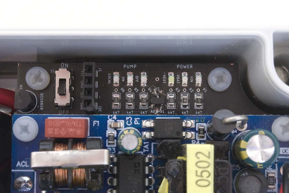
The 9575-BPHC PCB is currently configured with six, coloured, status LEDs. The LEDs are laid out in two groups of three, one group indicating pump status the other Node power status. For general operations, the pump status LEDs are probably the ones of most interest, indicating whether or not the pump is running and whether it is under local or remote control.
9575-BPHC Status LEDs
| Pump | Power | Status | |||||
|---|---|---|---|---|---|---|---|
| Local | ON | OFF | Vext | Vbat | Vin | ||
| No power | |||||||
| Pump OFF | |||||||
| Pump ON [Remote Control] | |||||||
| Pump OFF [Local Override] | |||||||
| Pump ON [Local Override] | |||||||
| Vext OFF, No battery, Vin ON | |||||||
| Vext OFF, Vbat ON, Vin OFF | |||||||
| Vext OFF, Vbat & Vin ON | |||||||
| Vext ON, No battery, Vin ON | |||||||
| Vext & Vbat ON, Vin OFF | |||||||
| Vext, Vbat & Vin ON | |||||||
Under normal circumstances, the Vin LED, indicating that the power supply is providing power to the processor, will always be lit. The Vbat LED will be lit when a battery is connected. Note, however, that when connected to a power source via the on-board USB connector, both the Vin and Vbat LEDs are lit, regardless of whether or not the power supply is switched on or a battery is present. The Vext LED will normally just flash when reading a sensor, because external power is only turned on when required.
Software
Note: There is a minor problem with the current board configuration in that it is not possible to plug a USB cable into the CubeCell Dev-Board with everything in place within the enclosure. This problem can be overcome by simply 'popping' the bottom of the SSR up off its mounting rail—it doesn't need to be removed, just raised up enough the provide access to the CubeCell Dev-Board USB socket.
At one level, this is quite a simple software application—we simply raise a digital signal on a processor pin, which activates the SSR to turn on the pump. The fact that the signal may be triggered either locally or remotely, the need to ensure that the appliance under control is only running when it should be, and the need to monitor the temperature of the SSR and turn it off if it gets too hot, make for a slightly more complicated exercise.
Process Sequencing
The issue of process sequencing is closely tied to the nature of the Reliable Packet Delivery Protocol (RPDP)—the fact that, first, there is no collision detection and, second, there is no buffering of incoming packets, the latter being of particular importance if the processor happens to be busy doing something else when an incoming packet arrives. In both of these cases, the packet, or packets, are lost and it is up to the Nodes involved to manage these conditions.
Both of these situations are managed, in the first instance, by simply resending packets that are not acknowledged, but only up to three times. The RPDP employs a simple, random retransmission timing mechanism to minimise the potential for two Nodes to inadvertently synchronise their transmission timing.
With regard to a Node's being able to process critical packets when they arrive, however, there is a little more that can be done. When a packet requiring acknowledgement is received, it needs to be acknowledged in a timely fashion. Similarly, when a packet requiring acknowledgement is sent, the sending Node needs to be ready to receive the acknowledgement when it arrives.
The packet processing sequence within a Node therefore needs to be managed at two levels—switching between transmit and receive modes and appropriately prioritising tasks when in transmit mode.
The main processing loop operates as a state machine, switching back and forth between transmit and receive modes. If, however, we have just sent a packet that requires acknowledgement, we do know that, if that packet is received, it will be acknowledged very soon thereafter. Accordingly, we need to ensure that we switch into receive mode as soon as we've sent out a packet that requires acknowledgement, regardless of whether or not the Node has other tasks that could be performed in the present processing cycle.
Processing Cycle
Our processing logic can therefore be summarised as follows:
- In transmit mode [TX_State] we have four possible tasks to perform:
- Check to see if we need to acknowledge receipt of a packet. We need to do this first because the sender is waiting for our response;
- If we have sensor data to send, we need to send that;
- Both of the following use RPDP, are thus time-sensitive and will be expecting an acknowledgement, requiring immediate subsequent transition to receive mode, so only one can be performed in each transmit mode cycle, with task a. taking priority over task b.:
- If a local pump state change has been triggered, we need to advertise the fact to the Gateway/MQTT broker;
- If we have packets that require acknowledgement, and need to be resent (because receipt of earlier attempts has not been acknowledged), we send them, but only one per cycle (although, in the present application, it is unlikely that there will ever be more than one to send).
- In receive mode [RX_State] we simply check the input buffer, process anything that's there, then switch to transmit mode [TX_State]. If we have just received a packet, and it requires acknowledgement, the required response will have been queued for transmission.
The 'high level' coding of this strategy is then as illustrated below.
Processing Logicstatic RadioEvents_t RadioEvents; typedef enum { TX_State, RX_State } States_t; States_t state; void setup() { . . RadioEvents.RxDone = OnRxDone; Radio.Init( &RadioEvents ); . . } void loop() { switch(state) { case TX_State: { if ( sendAck ) { [Send ACK packet] // sendAck is set, if acknowledgement is required (REL // bit set), when processing a received packet } if ( readSensors ) { [Read sensors and send status packets] // readSensor is set periodically by a timer } if ( changePumpState ) { [Toggle the pump state and send a status update packet] // changePumpState is set by an ISR in response to a // local button press } else if ( checkAckBuffer ) { [Check if there are any packets that need to be resent] // checkAckBuffer is set when sending a packet that // requires acknowledgement. The ACK buffer contains // RPDP packets that are yet to be acknowledged. } state = RX_State; break; } case RX_State: { Radio.Rx(0); Radio.IrqProcess( ); state = TX_State; break; } } } void OnRxDone( uint8_t *payload, uint16_t size, int16_t rssi, int8_t snr ) { // Process the incoming packet // If the packet requires acknowledgement (REL bit set) // set the sendAck flag } |
Reliable Transmission
As mentioned above, both the Gateway and Power Switch Nodes must cooperate in using the Reliable Packet Delivery Protocol (RPDP) to exchange messages with the MQTT broker. While communications between the Gateway Node and the MQTT Broker use the TCP protocol, and are thus 'reliable' at that level, there is no guarantee that this connection will be alive at the instant an MQTT message needs to be published.
Need a litte more discussion on this subject—what to do when the broker connection is lost. Currently, the Gateway is a bit useless if it can't forward relevant MQTT messages—that, after all, is its primary function. In fact, when the Gateway enters the broker-reconnect cycle it effectively blocks all incoming traffic. This may actually support a case to have the gateway and broker on the same host—this doesn't restrict the hardware platform to a Raspberry Pi though, as there are several MQTT broker solutions available for the ESP32.
MQTT
There's nothing really to be done with the MQTT broker configuration—in this case it's Mosquitto running on a Raspberry Pi—it just has to be running. All the rest is done by the publishers and subscribers—the Gateway Node and the Node-RED host.
The Gateway Node must be configured to both publish topic data provided by the Power Switch Node, and subscribe to the pump control topics published by the Node-RED host. The former are handled through the PacketHandler library function mqttOut(), the latter currently configured statically within the Gateway Node sketch. The ultimate goal is to have the latter provided automatically via some initial synchronisation process involving the Gateway Node and any Power Switch Node that it supports. All the necessary configuration information would then be stored in EEPROM and managed through the EepromHandler.
Node-RED
There's a little more to do on the Node-RED side of things. I have provided an overview of a basic Node-RED configuration on the Node-RED Software page and the discussion on the RPDP page.
Heartbeat Monitor
Messages are sent every minute, in each direction, to confirm the expected and actual status respectively of the Power Switch.
If the Power Switch Node does not receive confirmation of its intended status from the broker for 3 minutes—i.e. if three status messages in a row are missed—the power supply is automatically switched off.
At the moment, the Power Switch status reports are sent out at the same time as any [battery, temperature etc.] sensor reports, but not monitored by the MQTT broker to the extent that nothing happens if the reports stop—the status 'light' remains indicating the status according to the last message received. The broker should really turn the dashboard status light orange, or the like, if it hasn't heard from the Power Switch Node for 3 minutes, or whatever, to indicate that the Power Switch status is effectively unknown.
Note that the [Node-RED] Node status indicator will change, to red, if nothing at all is heard from the Node within the health check interval (by default, 5 × heartbeat interval)—maybe the pump status indicator should turn to orange then too.
Note also that there has been no discussion (at all!) in relation to the Node‑RED dashboard setup to this point, so any reference to what might be happening there will be quite meaningless until this particular 'shortcoming' has been addressed.
Enclosure Status Monitor
A DS18B20 digital temperature sensor is included to monitor the enclosure temperature so that, for example, the SSR can be switched off if the enclosure temperature gets too high.
Watchdog Timer
There's nothing much required on the software side here other than to 'pat the dog' at appropriate intervals. The requirement here is simply to raise the signal on the DONE pin ('pat the dog') more often than the [hardware] configured TPL5010 timeout interval.
Local vs Remote Control
Need a discussion here on the software elements of switch control—interrupts and timers.
The primary consideration here is the mechanism used to transition between Local and Remote Control Modes. Recall that this transition is signalled by pressing and holding a button for [at least] a predefined period of time—currently, 3 seconds.
There are then two software elements used to control the Mode in which the Node operates—interrupts and an asynchronous timer. In the present environment, interrupts operate much as they do on most Arduino platforms. Timers, however, on the CubeCell ASR650x platforms are managed through the on-board Real Time Clock (RTC). As such, we need to include some specific declarations and function calls to set up the timer we will use:
|
bool localControl = false; bool toggleButtonFlag = false; bool overrideTimerActive = false; uint32_t risingInterruptTime = 0; uint32_t fallingInterruptTime = 0; const uint32_t overrideTriggerInterval = 3000; // milliseconds static TimerEvent_t overrideTimer; TimerInit( &overrideTimer, setControlMode ); TimerSetValue( &overrideTimer, overrideTriggerInterval ); void setControlMode() { if ( localControl ) { localControl = false; digitalWrite( localControlLED, LOW ); // Turn Local LED OFF } else { localControl = true; digitalWrite( localControlLED, HIGH ); // Turn Local LED ON } overrideTimerActive = false; } |
Within the body of our sketch, we then proceed by attaching an interrupt to the rising edge of the signal generated when pressing the Toggle Button:
|
PINMODE_INPUT_PULLDOWN( toggleButton ); attachInterrupt( toggleButton, toggleButtonPressed, RISING ); void toggleButtonPressed() { risingInterruptTime = millis(); startOverrideTimer(); attachInterrupt( toggleButton, toggleButtonReleased, FALLING ); } void startOverrideTimer() { if ( overrideTimerActive ) { TimerReset( &overrideTimer ); } else { TimerStart( &overrideTimer ); overrideTimerActive = true; } } |
When the Toggle Button is pressed, the ISR (toggleButtonPressed()) will start the previously defined timer that will be used to measure how long the button remains pressed. Within this 'rising' ISR an interrupt is then attached to the falling edge of the signal generated by the button press.
|
startOverrideTimer(); attachInterrupt( toggleButton, toggleButtonReleased, FALLING ); void toggleButtonReleased() { fallingInterruptTime = millis(); attachInterrupt( toggleButton, toggleButtonPressed, RISING ); if ( fallingInterruptTime - risingInterruptTime < overrideTriggerInterval ) { if ( overrideTimerActive ) { TimerStop( &overrideTimer ); overrideTimerActive = false; } if ( localControl ) { toggleButtonFlag = true; } } } |
If the button is released before the timer expires, this 'falling' ISR (toggleButtonReleased()) stops the timer and, if Local Control Mode is active, simply toggles the pump state—if Remote Control Mode is active, the toggle request is ignored. If the button is not released before the timer expires, the Node switches modes—from Remote to Local or vice versa, depending on the mode that was active at the time the button is pressed—and the blue 'Local' LED set as appropriate—in Local Control Mode the blue 'local' LED is lit, in Remote Control Mode it is not.
Once in Local Control Mode, the above process effectively collapses into an interrupt (even though there are actually two), attached to the control button, that toggles the SSR that switches between ON and OFF states.
Testing the Configuration
Maybe include sketches that were used to test individual elements of the configuration—LEDs, watchdog timer, EEPROM configuration and temperature and current sensors.
For the time being, the Arduino > Software > Node Setup & Test page includes such test sketches as are currently available.
Power Switch Application
The Power Switch application sketch and support files can be downloaded through the links provided below. I'll provide a complete description of what's going on at some point, but for the time being the reader will need to look at the various PacketHandler pages, the RPDP page in particular, for information on the specific details of the communications protocol used in this application.
Refer to the PacketHandler Downloads page for details on the required support libraries and files.
If running on a Heltec CubeCell module, as is currently configured, this sketch also requires a current version of the Heltec [CubeCell] hardware support libraries.

|
Power Switch Node [0.0.31] [CubeCell] |
03-Jun-2024 | [12 KB] |

|
Gateway Node [0.0.23] [WiFi LoRa 32 V3] |
28-Feb-2024 | [14 KB] |


