MPS20N0040D Air Pressure Sensor
Application
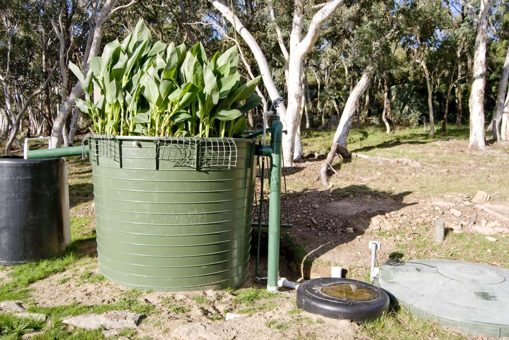
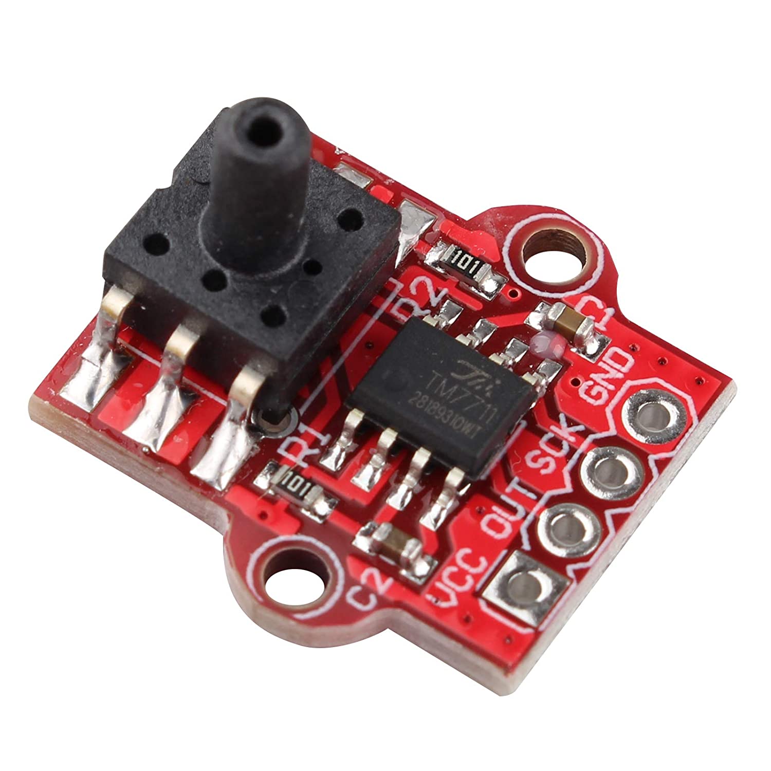
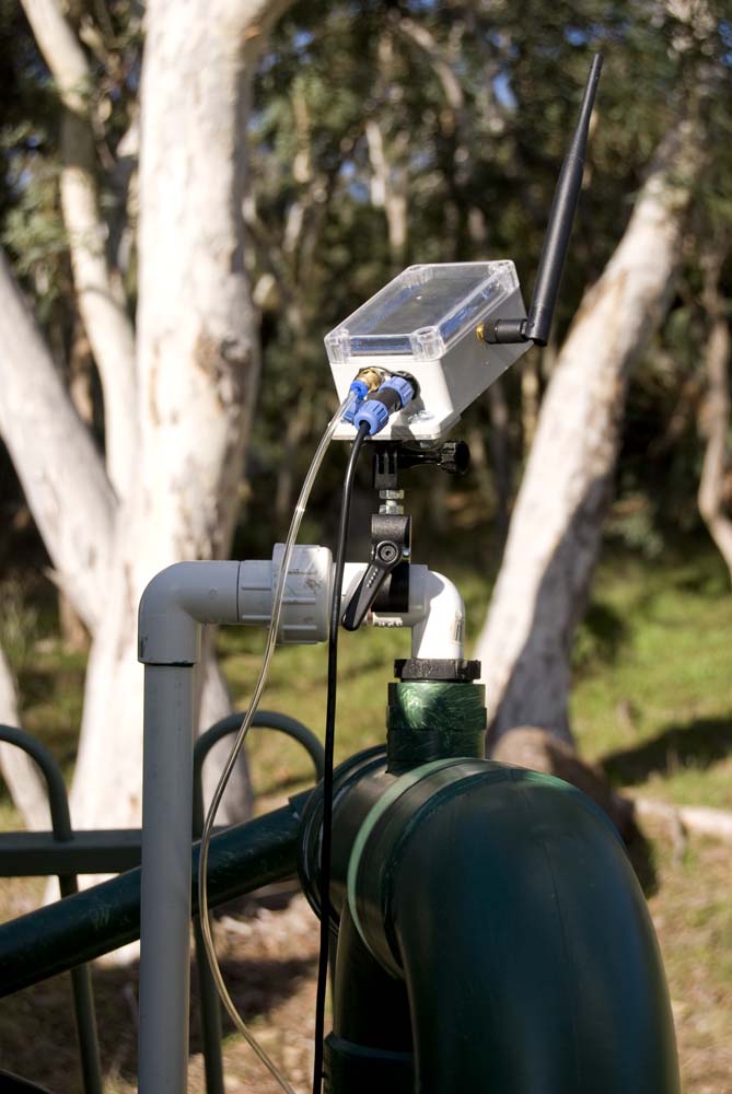
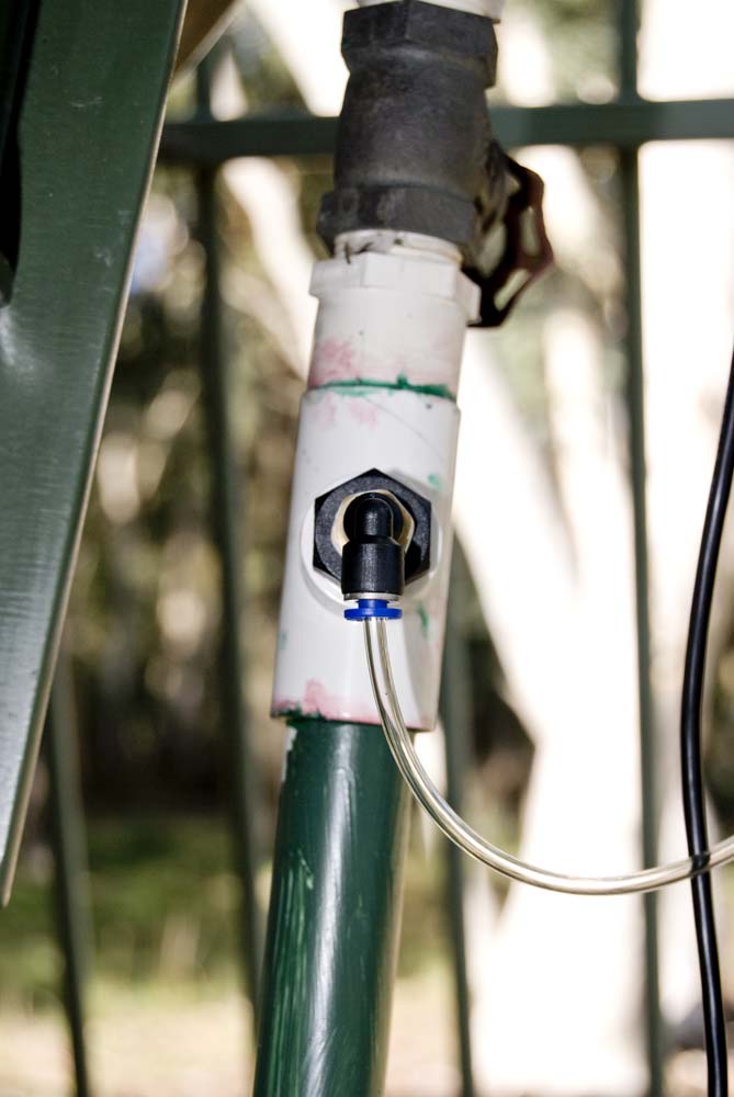
This Air Pressure Sensor module, an MPS20N0040D sphygmomanometer mated with an HX710B analog-to-digital converter, is currently used to monitor air pressure in the blower [compressed air] line on an aerated wastewater treatment system (AWTS).
| Node | Pressurised Air Line |
|---|---|
 |
 |
AWTS Node Installation
This node also monitors the water level in the main AWTS influent tank using an ultrasonic distance measuring sensor.
Configuration
Hardware
Since this module does not use a standard I2C interface, a compromise must be made when using any of our preconfigured prototyping boards. The module requires two lines, and can be used on those normally allocated to the I2C interface, but then the I2C interface is no longer available for any other sensors.
The alternative, if providing connectivity through the A4a sensor interface, is to use the two lines normally allocated for use with the timer and battery monitoring circuits. Either configuration works fine, it's just a question of what features can be sacrificed.
As the CubeCell modules have their own on-board battery management circuitry, and an effective low power (sleep) mode, the two aforementioned A4a sensor interface pins are always available for sensor management. At this early stage, the CubeCell Module Plus offered the added advantage of having a built-in display to help with initial configuration where the node could not easily be connected to a computer with a Serial Monitor.
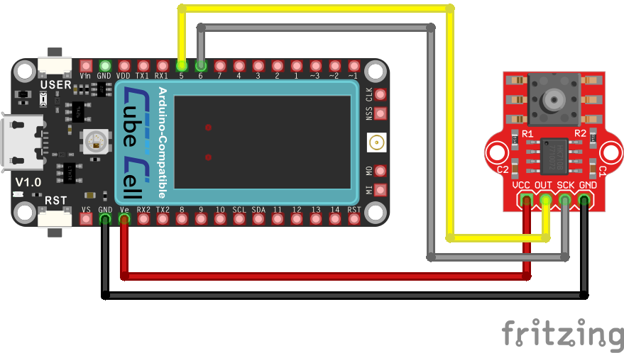
The current CubeCell Dev-Board Plus configuration is as illustrated below.
CubeCell Dev-Board Plus–Air Pressure Sensor Electrical Circuit
Pin Configuration
| CubeCell Plus | MPS20N0040D |
|---|---|
| GND | GND |
| Ve | VCC |
| GPIO5 | OUT |
| GPIO6 | SCK |
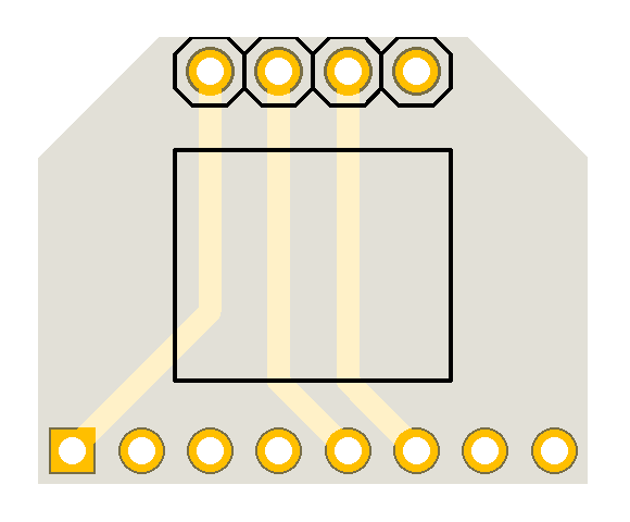
The actual physical configuration, as currently implemented, is based on the 10068-BHCP base board, and uses a specifically designed piggy-back adaptor board to connect the [4-pin] sensor module to the necessary pins on the [8-pin] A4a sensor interface.
| Top | Bottom |
|---|---|
 |
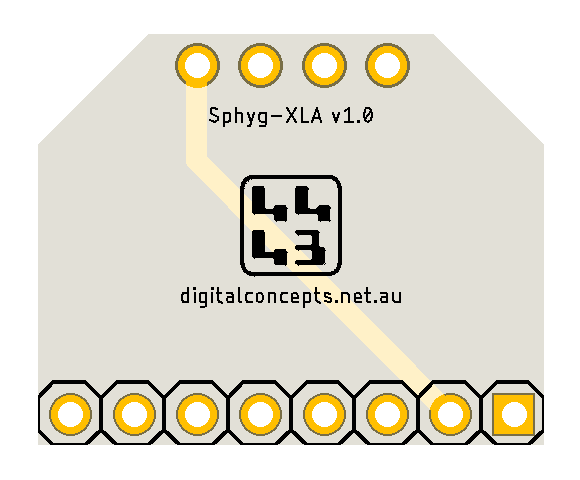 |
MPS20N0040D Sphyg-XLA Adaptor PCB

|
Sphyg-XLA Eagle CAD Files | [14 KB] |

|
Sphyg-XLA CAM Files | [20 KB] |
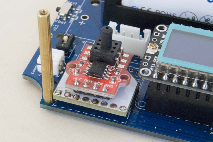
When assembling these 'piggy back' boards, the pins on the two headers should be trimmed to be flush with the PCB (as per the Sphyg-XLA board in the photo below) so as not to interfere with the mating header when boards are being plugged together.
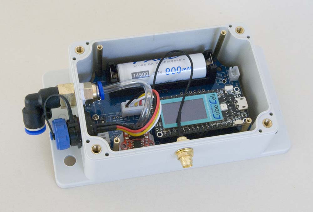
| Air Pressure Sensor Assembly | AWTS Node Configuration |
|---|---|
 |
 |
AWTS Node
While the tube couplings that I originally used on the enclosure (as illustrated above, right) are not really designed for use in a bulkhead, a good seal can still be achieved with liberal use of teflon plumbing tape. I subsequently found an actual panel mount fitting, which is what I now use in this role.
Note: It's much easier to install the 2.5 mm plastic tube between the pressure sensor and outlet coupling (per photo above, right) if it's warmed up with a heat gun or the like.
Software
The processor interface to the line pressure module is provided by the on-board HX710B analog-to-digital converter (ADC). There is an Arduino library designed specifically for the HX710B ADC (HX710B_Arduino), but I had no success in getting it working with my CubeCell configuration. There are also several libraries designed for the HX711 ADC, a common interface to electronic load cells (scales), and these are also claimed to generally support the HX710A/B ADC. Once again, however, I could not get most of these to work with the CubeCell configuration. I finally found some success with the HX711_ADC library, by Olav Kallhovd, although I cannot confess to fully understand the entire range of functions provided by this library.
The present application really only requires the node to report whether or not the air in the system is pressurised. In practice, the pressure in the line is either ~15kPa (normal operations) or zero (blower not working, or line failure) [above atmospheric pressure].
This application also makes 'taring' a little difficult in that the state of the blower line cannot be guaranteed at any point in time, and it is not practical to disconnect the sensor (to tare to atmospheric pressure) every time the node is reset. Even so, I have noticed that the sensor is capable of measuring the natural variation in atmospheric pressure, so I'm not sure what good taring to atmospheric pressure at one point in time would be in any case. Either way, for the time being at least, I am only interested in whether or not the line is pressurised, not the exact pressure in the line.
This is fortunate because another problem that remains is that, in spite of the claim that this sensor measures over a range of 0–40kPa, and my blower has a claimed maximum output of just 16kPa, the sensor is constantly maxed out when connected to an operational line. The measured pressure does at least fall significantly when the blower is not operating, so, for the time being, the necessary information is being provided.
The sensor is described as a differential transducer, so it may be that it measures something like ambient pressure +/- 20kPa, for a range of 40kPa, but even so, I would have expected to be able to comfortably accommodate a reading of [ambient +] 16kPa, that being the rated output of the blower in use. It may, however, simply be a case of bringing one's expectations into line with the cost/quality of this particular sensor.
Indeed, this article, on the Maker Portal blog, provides a comprehensive explanation of how this sensor works. This analysis indicates that the range of the pressure sensor itself is, amongst other things, 'clipped' by the way it has been configured with the on-board HX710B ADC, so that it's actual measurement range may be as narrow as -13kPa to +10kPa.
On this basis, the resting point of the sensor [when the blower is not operating] would be atmospheric pressure, and the maximum positive pressure that could be recorded would be around 10kPa, well below the 16kPa rated maximum of my blower, and a good reason why the sensor in my configuration might be constantly maxed out.
Testing the Configuration
The following sketch, which runs on the CubeCell Dev-Board Plus in the configuration illustrated above, is largely based on the Testing example provided with the HX711_ADC library. To assist with testing when a Serial Monitor is not available, the present version also generates output on the built-in display on the CubeCell Dev-Board Plus.
CubeCell Dev-Board Plus sketches use the pin identifiers defined in the CubeCellPlusPins.h file.
1 2 3 4 5 6 7 8 9 10 11 12 13 14 15 16 17 18 19 20 21 22 23 24 25 26 27 28 29 30 31 32 33 34 35 36 37 38 39 40 41 42 43 44 45 46 47 48 49 50 51 52 53 54 55 56 57 58 59 60 61 62 63 64 65 66 67 68 69 70 71 72 73 74 75 76 77 78 79 80 81 82 83 84 85 86 87 88 89 90 91 92 93 94 95 96 97 98 99 100 101 102 |
#include <HX711_ADC.h>// HX711 ADC library
#include <HT_SH1107Wire.h>// CubeCell Plus display library #include "CubeCellPlusPins.h"// CubeCell Plus pin definitions // Define the pins to be used const int HX711_dout = sphygOUT;// MCU > HX711 dout pin const int HX711_sck = sphygSCK;// MCU > HX711 sck pin // HX711 constructor HX711_ADC LoadCell(HX711_dout, HX711_sck); // The CubeCell Plus Display object SH1107Wire display(0x3c, 500000, SDA, SCL, GEOMETRY_128_64, GPIO10);// addr, freq, sda, scl, resolution, rst unsigned long t = 0; void setup () { pinMode(Vext,OUTPUT); digitalWrite(Vext,LOW);// Turn on power to connected devices Serial.begin(115200); delay(10); Serial.println(); Serial.println("[setup] Starting..."); display.init(); display.setFont(ArialMT_Plain_10); display.screenRotate(ANGLE_180_DEGREE); display.clear(); float calibrationValue;// Calibration value calibrationValue = 1000000.0;// A simple scaling factor that is convienient for the present test LoadCell.begin(); unsigned long stabilizingtime = 2000;// Tare preciscion can be improved by adding a few seconds of stabilizing time boolean _tare = false;// Set this to false if you don't want tare to be performed in the next step LoadCell.start(stabilizingtime, _tare); if (LoadCell.getTareTimeoutFlag()) { Serial.println("[setip] Timeout, check MCU>HX711 wiring and pin designations"); } else { LoadCell.setCalFactor(calibrationValue);// Set calibration factor (float) Serial.println("[setup] Startup is complete"); } while (!LoadCell.update()); Serial.print("[setup] Calibration value: "); Serial.println(LoadCell.getCalFactor()); Serial.print("HX711 measured conversion time ms: "); Serial.println(LoadCell.getConversionTime()); Serial.print("HX711 measured sampling rate HZ: "); Serial.println(LoadCell.getSPS()); Serial.print("HX711 measured settlingtime ms: "); Serial.println(LoadCell.getSettlingTime()); Serial.println("[setup] Note that the settling time may increase significantly if you use delay() in your sketch!"); if (LoadCell.getSPS() < 7) { Serial.println("[setup] Warning: Sampling rate is lower than specification, check MCU>HX711 wiring and pin designations"); } else if (LoadCell.getSPS() > 100) { Serial.println("[setup] Warning: Sampling rate is higher than specification, check MCU>HX711 wiring and pin designations"); } } void loop() { static boolean newDataReady = 0; const int serialPrintInterval = 500;//increase value to slow down serial print activity // Check for new data/start next conversion: if (LoadCell.update()) newDataReady = true; // Get smoothed value from the dataset: if (newDataReady) { display.clear(); if (millis() > t + serialPrintInterval) { float i = LoadCell.getData(); Serial.print("[loop] Load_cell output val: "); Serial.println(i); display.clear(); display.setFont(ArialMT_Plain_10); display.drawString(10, 5, "Presaure Reading:"); display.setFont(ArialMT_Plain_16); char charData[8]; dtostrf(i,8,2,charData); display.drawString(10, 20, charData); display.display(); newDataReady = 0; t = millis(); } } // Receive command from serial terminal, send 't' to initiate tare operation: if (Serial.available() > 0) { char inByte = Serial.read(); if (inByte == 't') LoadCell.tareNoDelay(); } // Check if last tare operation is complete: if (LoadCell.getTareStatus() == true) { Serial.println("[loop] Tare complete"); } } |
There was, however, more to do to get this working in our environment. A problem that I have faced on several occasions is dealing with the consequences of powering down a sensor when entering low power mode, then restoring the sensor to an appropriate state when required to take a subsequent reading.
In the present case, several measurements need to be made after any significant change in pressure before a consistent measurement can be recorded. This doesn't appear to be just a time interval, it seems that several readings (typically about 5) actually need to be made before the sensor produces consistent results.
AWTS Application
This section is not complete—I am currently migrating all applications to use my PacketHandler library, so there may be a bit of a disconnect here until that's done.
The Aerated Waste Treatment System (AWTS) application sketch and support files can be downloaded by clicking on the following links. I'll provide a complete description of what's going on at some point, but for the time being you'll need to look at the descriptions under each of the relevant sensors to see what's happening in each case.
Place the PacketHandler library folder in the Arduino/libraries folder.

|
PacketHandler library package | [21 KB] |
Place the Langlo folder, containing the Langlo header files, in the Arduino/libraries folder. The Langlo folder, and the files it contains, can be renamed anything you like.

|
Langlo header files | [15 KB] |
Place the AWTS Node sketch folder in the Arduino IDE root folder (Arduino). If running on a Heltec CubeCell Plus module, as is currently configured, this sketch also requires the latest version of the Heltec [CubeCell] hardware support libraries.

|
AWTS Node sketch | [7 KB] |


