

RS485 Interface
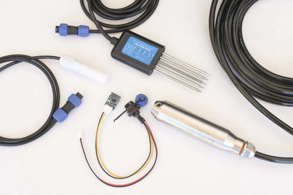
I'm just beginning my exploration of RS485 communications, but I'll keep adding details as I progress through this exercise.
TTL to RS485 Adaptors
I started off knowing absolutely nothing about RS485 communications although I had worked with RS232 communications back in the day, before the existence of 'modern' PCs, when an Ethernet trunk was a half-inch coaxial cable used to connect mainframe computers and serial protocols were the most general means by which terminal devices communicated with their host. I did get the idea that some sort of interface module was going to be required in the present environment but the first confusing thing I had to deal with was the array of different interface adaptor configurations that existed.
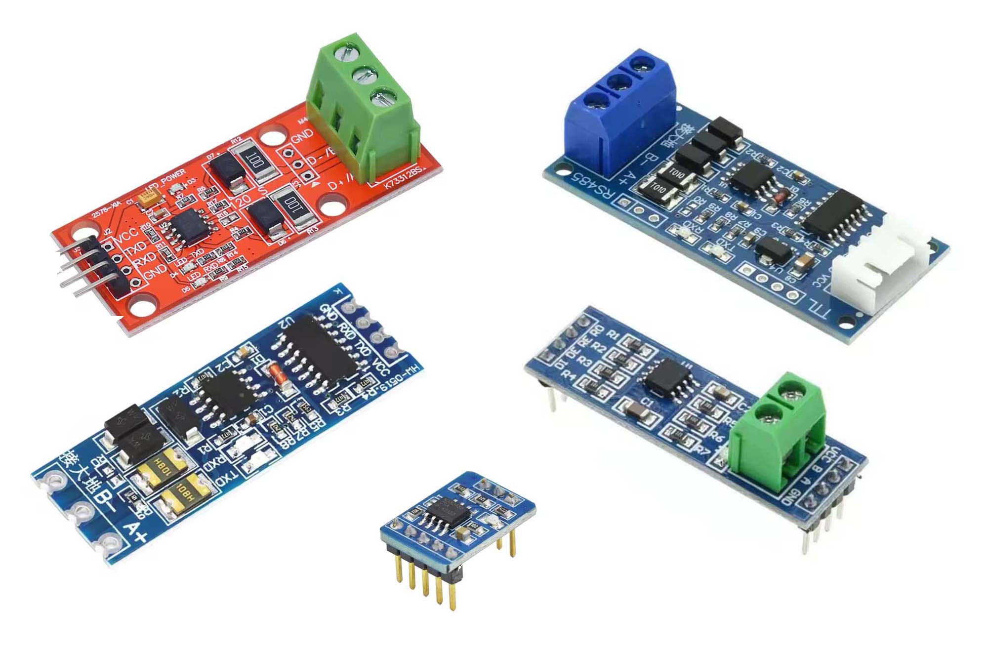
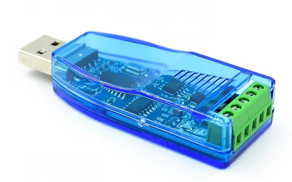
Some of the available RS485 Interface Adaptors
Ultimately, I'll try to get to the bottom of the implications of the obvious component differences between the various modules. Some clearly have an additional IC, a CD4069UB hex inverter (i.e. the IC comprises six inverters), and these modules also have what is described on some sites as lightening protection circuitry—a pair of thermal recovery fuses and several bidirectional TVS transient suppression diodes—so these modules are doing 'more' than the others although it's not clear to me at this point that this additional functionality is required in my environment.
Some of these adaptors also appear to require physical signalling to set the host device in transmit or receive mode while others seem to manage this automatically. The two configurations would clearly have different connectivity requirements at both hardware and software levels so it seemed that coding was going to have to take this sort of thing into consideration.
On close inspection another difference became apparent—some of the modules were based on the MAX485 IC while others used the newer, faster (although this is pretty much irrelevant in the present case given the speed of the sensors we will be using) MAX3485 IC. Either way, the name of these devices, TTL UART-to-RS485 interface adaptors, also gave a hint that they would need to be connected to a UART, not to just any pins on a processor board.
Different processors have different ways in which they use their UARTs, when they have more than one—of course, processor modules like the Arduino Pro Mini don't even have a UART!—so this was the first issue to be addressed. To date, I have only used the single RS485 adaptor illustrated below, initially in conjunction with a RS485-to-USB adaptor, in my testing, primarily because it appeared to be one that did not require any special programming in relation to setting send or receive mode on the RS485 bus. I figured that, if I needed to deal with manual traffic control at some point, I'd tackle that problem when it presented itself.
RS485 Communications
Heltec CubeCell Dev-Board Plus
I started with a simple test that involved connecting a CubeCell Dev-Board Plus, because it has two explicitly defined UARTs, to one of my Mac hosts. This basic configuration required the use of a UART-to-RS485 adaptor on the CubeCell Dev-Board Plus and an RS485-to-USB adaptor on the Mac and turned out to be relatively straightforward.
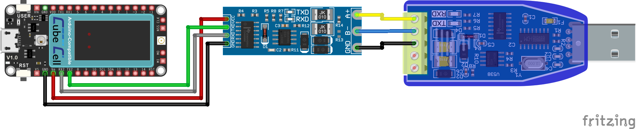
CubeCell Plus RS485 Electrical Circuit
Pin Configuration
| CubeCell Plus | UART-to-RS485 | RS485-to-USB |
|---|---|---|
| GND | GND | |
| UART_TX2 | Tx | |
| UART_RX2 | Rx | |
| Vext | Vcc | |
| A+ | A | |
| B- | B | |
| Sig-GND | GND | |
In this configuration, the CubeCell Plus and the USB adaptor are powered through their respective USB connections.
The test sketch here, which just sends and receives text messages over the RS485 connection and runs on the CubeCell Plus, is also very simple, essentially just writing to and reading from the RS485 serial port.
/*
   This simple sketch can be used to demonstrate an operational RS485 connection.
   It uses SoftwareSerial, and assumes that you have a TTL-to-RS485 adaptor connected
   to the second CubeCell Dev-Board Plus UART (UART_TX2/UART_RX2) and some other
   RS485-connected device that can send and received messages. Set sendLoop to true
   to just cycle sending messages or false to send and receive messages manually.
*/

#include <softSerial.h>

#define sendLoop true
#define RS485BaudRate 9600

int counter = 0;
String receiveString, sendString;

// Define the serial entity for connection to the RS485 adaptor
softSerial RS485(UART_TX2, UART_RX2);

void setup() {

  // Supply power to the RS485 adaptor

  pinMode(Vext, OUTPUT);
  digitalWrite(Vext, LOW);

  // Open the serial ports

  Serial.begin(115200);
  RS485.begin(RS485BaudRate);

  Serial.println("[setup] CubeCell Plus RS485 Test");
}

void loop() {
  if ( sendLoop ) {
    // Just loop around sending messages
    writeHelloWorld();
    // But also check for anything we might receive...
    if ( RS485.available() > 0 ) {
      receiveString = RS485.readString();
      Serial.print("[loop] Received string: ");
      Serial.println(receiveString);
    }
  } else {
    // If we've got something to send...
    if ( Serial.available() > 0 ) {
    // Read input from the local Serial Monitor
      sendString = Serial.readString();
    // echo the input locally
      Serial.print("[loop] Input string: ");
      Serial.println(sendString);
    // then send it out on the RS485 bus
      processInput(sendString);
      promptForInput();
    }
    // If we've received anything...
    if ( RS485.available() > 0 ) {
      // Report anything we receive on the RS485 bus
      receiveString = RS485.readString();
      Serial.print("[loop] Received string: ");
      Serial.println(receiveString);
    }
  }
  delay(1000);
}

void writeHelloWorld() {
  Serial.print("[loop] Sending '[");
  Serial.print(++counter);
  Serial.println("] Hello World!'...");
  RS485.print("[");
  RS485.print(counter);
  RS485.println("] Hello World!");
}

void processInput( String inputString ) {
  RS485.print("[From Remote Host] ");
  RS485.println(inputString);
}

void promptForInput() {
    Serial.println("[loop] Type in your message and press <return>...");
}
To view messages at the host end—the USB side of the RS485-to-USB adaptor—I simply opened a second, empty sketch under the Arduino IDE, linked it to the port associated with the USB adaptor, and opened the Serial Monitor panel. If the Serial Monitor panel on the CubeCell Plus sketch/port is also opened, one can see the messages being sent and received at both ends of the RS485 connection.
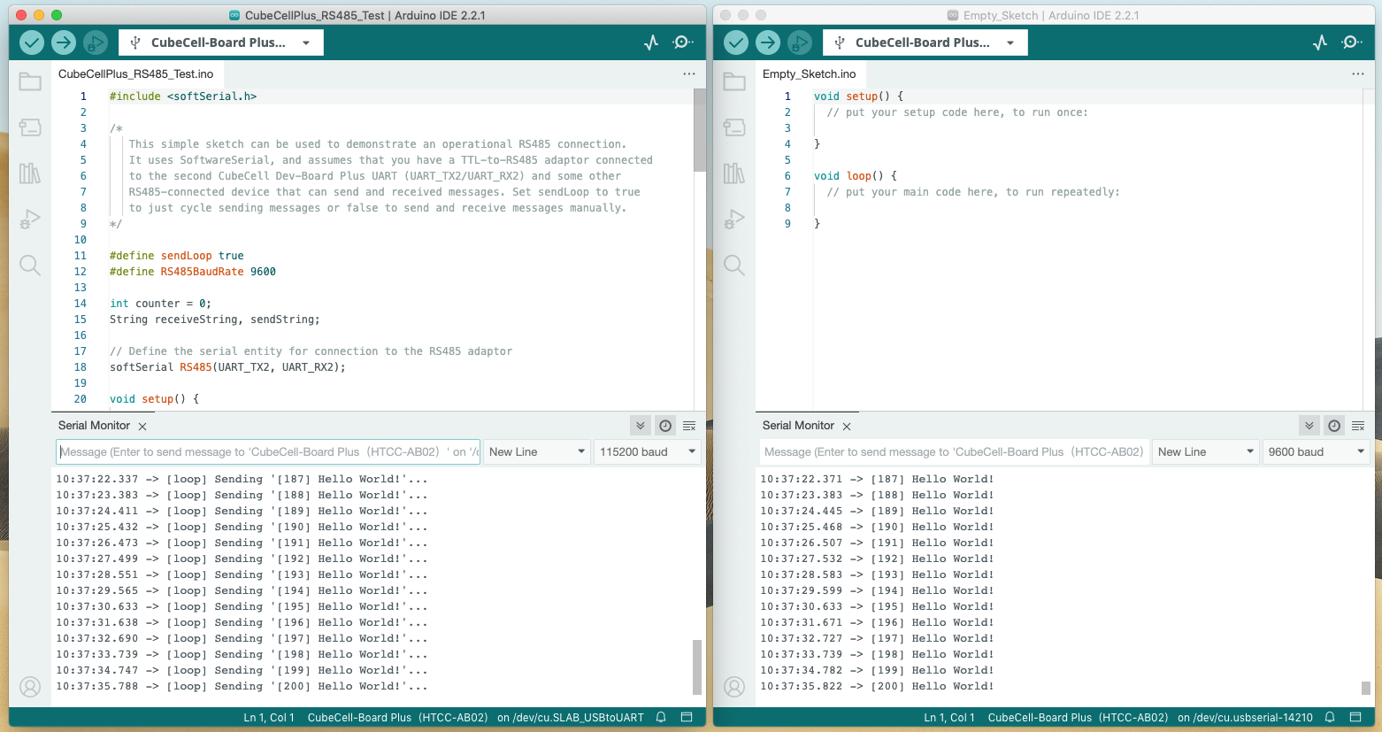
RS485 Test Output — IDE Serial Monitor
Communications with individual sensors could then be explored with some degree of confidence that messages were actually being sent out the RS485 interface.
Having successfully carried out all of the testing, with the various sensors described in this section, using the [MAX485-based] TTL‑to‑RS485 adaptor illustrated in the various configuration diagrams, I returned to this exercise to test the operation of the much smaller, MAX3485-based adaptor (the small one in the photos at the top of this page), as this form factor would have been much easier to incorporate into my application hardware. In the event, I have failed miserably to get this module to work. It's unlikely to be the MAX3485 IC that's the problem here, more likely my lack of understanding in relation to the function of the additional components on the other, larger adaptors.
Running the simple configuration described above, with the addition of a connection from the adaptor EN pin to the CubeCell VDD pin, the output generated by the receiving host (via the USB-to-RS485 adaptor) was largely the sort of gibberish you see when you've got a baud rate mismatch, but no amount of fiddling with different baud rates improved the situation. On occasion, there were correctly represented fragments of the sent messages amongst the gibberish, but nothing consistent. I was unable to send anything in the opposite direction, no matter whether I had the EN pin set high or low. Maybe all that was missing were some appropriate balancing and pull-up/pull-down resistors but, if that were the case, and additional circuitry were to be required, this adaptor would be somewhat less attractive.
CAUTIONARY NOTE
At one point, one of these MAX3485-based adaptors (I had three, and tried them all just in case I had a dud, or two) got very hot, as did [I believe it would have been] the regulator on my host CubeCell Dev‑Board Plus, but I could not identify any difference between the configuration I was using at the time and any other that I had used previously without issue. I discarded that particular adaptor, but still I did not meet with any success working with the other two. I frequently swapped back to the original MAX485-based adaptor that had always 'just worked', to check that there were not any problems elsewhere in my set-up and, every time I did this, the MAX485-based adaptor worked flawlessly.
To add insult to injury, having once again reconnected the MAX3485‑based adaptor, the CubeCell Dev-Board Plus module I was using suddenly went into a permanent reboot cycle, never to recover! Sketches appeared to load successfully, but the module never booted successfully. On checking the voltage at the supply pins, the VDD pin was only registering ~1.6V so I suspect that some of the magic smoke escaped from the regulator, and maybe some other critical components, during the overheating incident. At this point I lost interest in this particular MAX3485 adaptor...
Heltec CubeCell Dev-Board
Configuring the CubeCell was a little more complicated because it only has a single [accessible] UART and this is normally used to upload software and monitor serial output. Using this UART for RS485 communications requires software to first be uploaded and the CubeCell USB connection to its programming host to then be disconnected before executing the loaded software in order to avoid any interference between the two functions. The only real issue here is that, without using the onboard LoRa radio to report progress, we are restricted to viewing messages received by the RS485-USB host to see what's going on. This is not so much of a problem in our case as we have already established that our overall configuration is OK using the CubeCell Plus platform.
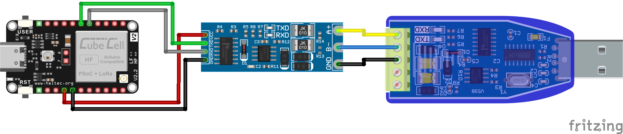
CubeCell RS485 Electrical Circuit
Pin Configuration
| CubeCell | UART-to-RS485 | RS485-to-USB |
|---|---|---|
| GND | GND | |
| TX | Tx | |
| RX | Rx | |
| Ve | Vcc | |
| A+ | A | |
| B- | B | |
| Sig-GND | GND | |
From the softare perspective, the existence of a single UART makes things even more simple. There is no need for SoftwareSerial since we are now simply using the predefined hardware serial interface.
/*
	This simple sketch can be used to demonstrate an operational RS485 connection.
	It uses the CubeCell serial UART, assumes that you have a TTL-to-RS485 adaptor
	connected to the Tx/Rx pins on the CubeCell Dev-Board and some other
	RS485-connected device that can send and received messages. Set sendLoop to true
	to just cycle sending messages or false to send and receive messages manually.
*/

#define sendLoop true
#define RS485BaudRate 9600

int counter = 0;
String dataString;

void setup () {

	// Supply power to the RS485 adaptor

	pinMode(Vext, OUTPUT);
	digitalWrite(Vext, LOW);

	// Open the serial port at the appropriate baud rate

	Serial.begin(RS485BaudRate);
}

void loop() {
	if ( sendLoop ) {
		// Just loop around sending messages
		Serial.print("[");
		Serial.print(++counter);
		Serial.println("] Hello World!");
		delay(1000);
	} else if ( Serial.available() > 0 ) {
		// If we've received anything, let the sender know...
		dataString = Serial.readString();
		Serial.print("[CubeCell] Message received : ");
		Serial.println(dataString);
	}
}
Note that when loading software, the RS485 adaptor should be disconnected from the CubeCell to avoid any interference with communications during the load process.
Note also that, sometimes after loading such a sketch, the Arduino IDE did not recognise subsequent reconnection of my CubeCell Dev-Board. On the assumption that this behaviour was related to the fact that the serial port had been reconfigured, I did two things. First, I set the Serial Monitor interface speed to 9600 baud. If nothing else, this allowed me to see any output from the CubeCell while its serial port was set at that speed. The next thing, in response to an error message indicating failure to communicate with the bootloader, was to manually put the CubeCell into boot mode by holding the USER button down while pressing the RST button—this should generate an appropriate confirmation message in the Serial Monitor, something like:
|
Copyright @2019-2020 Heltec Automation.All rights reserved. bootloader Rev 1.0 |
Sometimes I had to power cycle the board a couple of times and reconnect the USB cable, but it ultimately came good. I could then proceed to upload a new sketch.
Heltec WiFi LoRa 32 / Wireless Stick Lite
The ESP32 does things a little differently with regard to assigning pins to its UARTs, of which it has three. The fundamentals of UART usage on the ESP32 are presented in the Espressif documentation, but there is also some practical implementation advice in this Random Nerd Tutorial, in particular perhaps that relating to pin assignments on the C3 (pre-V3 Heltec ESP32 boards) vs S3 (V3 and later Heltec ESP32 boards) processors. Note also that the default pins for the second and third UARTs are not broken out on the WiFi LoRa 32 V3 and later boards, so appropriate pins have to be assigned explicitly.
The following sketch performs the same functions as those previously presented for use with the CubeCell platforms. The only real difference is the use of HardwareSerial, and its initialisation process, on the ESP32 rather than the softSerial interface used with the CubeCell Plus platform.
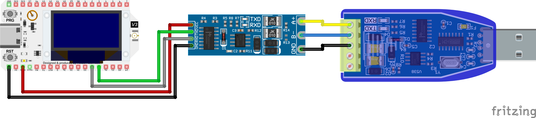
WiFi LoRa 32 V3 RS485 Electrical Circuit
Pin Configuration
| WiFi LoRa 32 (V3) | UART-to-RS485 | RS485-to-USB |
|---|---|---|
| GND | GND | |
| GPIO48 | Tx | |
| GPIO47 | Rx | |
| Ve | Vcc | |
| A+ | A | |
| B- | B | |
| Sig-GND | GND | |
/*
   This simple sketch can be used to demonstrate an operational RS485 connection.
   It uses the ESP32 HardwareSerial, and assumes that you have a TTL-to-RS485 adaptor
   connected to the second ESP32 UART (TX 48/RX 47) on the WiFi LoRa 32 V3 board and some
   other RS485-connected device that can send and received messages. Set sendLoop to true
   to just cycle sending messages or false to send and receive messages manually.
*/

#define sendLoop true
#define RS485BaudRate 9600

int counter = 0;
String receiveString, sendString;

// Define the serial entity for connection to the RS485 adaptor
HardwareSerial RS485(2);

void setup() {

  // Supply power to the RS485 adaptor

  pinMode(Vext, OUTPUT);
  digitalWrite(Vext, LOW);

  // Open the serial ports

  Serial.begin(115200);
  RS485.begin(RS485BaudRate, SERIAL_8N1, 47, 48);   // Baud, bits, Rx, Tx

  Serial.println("[setup] WiFi LoRa 32 V3 RS485 Test");
}

void loop() {
  if ( sendLoop ) {
    // Just loop around sending messages
    writeHelloWorld();
    // But also check for anything we might receive...
    if ( RS485.available() > 0 ) {
      receiveString = RS485.readString();
      Serial.print("[loop] Received string: ");
      Serial.println(receiveString);
    }
  } else {
    // If we've got something to send...
    if ( Serial.available() > 0 ) {
    // Read input from the local Serial Monitor
      sendString = Serial.readString();
    // echo the input locally
      Serial.print("[loop] Input string: ");
      Serial.println(sendString);
    // then send it out on the RS485 bus
      processInput(sendString);
      promptForInput();
    }
    // If we've received anything...
    if ( RS485.available() > 0 ) {
      // Report anything we receive on the RS485 bus
      receiveString = RS485.readString();
      Serial.print("[loop] Received string: ");
      Serial.println(receiveString);
    }
  }
  delay(1000);
}

void writeHelloWorld() {
  Serial.print("[loop] Sending '[");
  Serial.print(++counter);
  Serial.println("] Hello World!'...");
  RS485.print("[");
  RS485.print(counter);
  RS485.println("] Hello World!");
}

void processInput( String inputString ) {
  RS485.print("[From Remote Host] ");
  RS485.println(inputString);
}

void promptForInput() {
  Serial.println("[loop] Type in your message and press <return>...");
}
RS485 Sensors
I purchased three RS485 sensors to work with in this exercise—a 7-in-1 Soil Condition sensor, an SHT30 Temperature & Humidity sensor and a QDY30A Water Level [Pressure] sensor—in part because I already had experience with similar sensors using different interface mechanisms. In the event, I don't think this experience was at all relevant in sorting out the nuts and bolts of the RS485 interface but it did allow me to compare measurements reported by the different sensors, something that was of broader interest in any case.

Generic RS485 Sensor Configuration Circuit
Pin Configuration
| CubeCell Plus | UART-to-RS485 | Sensor |
|---|---|---|
| GND | GND | |
| UART_TX2 | Tx | |
| UART_RX2 | Rx | |
| Vext | Vcc | |
| Vin | Vcc | |
| A+ | A | |
| B- | B | |
| Sig-GND | GND |
Full details of individual sensor configurations are provided in the pages accessible through the above hyperlinks or the left side menu. Only one of these sensors, however, came with any documentation beyond the identification of the respective RS485 wire connections. Fortunately, they all turned out to be more or less the same as items better described through documentation that was available on-line, although like many on-line resources, the trick was actually locating the relevant documents.
As it turned out, all of these sensors are controlled using the Modbus RTU protocol so the sensor management exercise in each case simply boiled down to one of identifying the content of the relevant queries and responses. The documentation on the ComWinTop website, while not for exactly the same sensors, is therefore close enough to enable the assembly of valid queries.
The following sketch provides the general framework required to assemble query strings and to transmit and receive them on the RS485 bus using the CubeCell Plus hardware configuration illustrated above. More detail on the format of individual queries is provided in the pages, accessible through the left side menu, describing the individual sensors.
#include <softSerial.h>

/*
   A simple sketch to test RS485 communications with Modbus RTU sensors.
   It uses SoftwareSerial, and assumes that we have a TTL-to-RS485 adaptor connected
   to the second CubeCell Dev-Board Plus UART (UART_TX2/UART_RX2) and the sensor under
   test.
*/

// Define baud rate as appropriate
// 7-in-1 Soil Condition          4800 (default)
// SHT30 Temperature & Humidity   9600 (default)
// QDY30A Water Level             9600 (default)

#define RS485BaudRate 9600

int counter = 0;
String receiveString, sendString;

// The following are valid query strings for the listed sensors. Remove the comment prefix
// from the query that is to be sent. For more detail, refer to the pages for individual
// sensors.

// 7-in-1 Soil Condition
//byte queryData[]{ 0xFF, 0x03, 0x07, 0xD0, 0x00, 0x01, 0x91, 0x59 }; // Broadcast Enquire Slave ID
//byte queryData[]{ 0x01, 0x06, 0x07, 0xD0, 0x00, 0x02, 0x08, 0x86 }; // Set Slave ID to 2
//byte queryData[]{ 0x01, 0x06, 0x07, 0xD1, 0x00, 0x02, 0x59, 0x46 }; // Set Baud to 9600

// SHT30 Temperature & Humidity
//byte queryData[]{ 0x00, 0x03, 0x07, 0xD0, 0x00, 0x01, 0x85, 0x56 }; // Broadcast Enquire Slave ID

// QDY30A Water Level
byte queryData[]{ 0x00, 0x03, 0x00, 0x00, 0x00, 0x01, 0x85, 0xDB }; // Broadcast Enquire Slave ID

byte receivedData[20];  // Size set as required by individual sensors

// Define the serial entity for connection to the RS485 adaptor

softSerial RS485(UART_TX2, UART_RX2);

void setup() {

  // Supply power to the RS485 adaptor

  pinMode(Vext, OUTPUT);
  digitalWrite(Vext, LOW);

  // Open the serial ports

  Serial.begin(115200);        // To the Serial Monitor
  RS485.begin(RS485BaudRate);  // To the RS485 bus
  delay(500);

  Serial.println("[setup] CubeCell Plus RS485 Sensor Test");
}

void loop() {

  // Send the query...
  // Note that a Set query (e.g. baud rate or Slave ID) may result in loss of
  // communication until sketch RS485BaudRate or query strings are adjusted to match

  Serial.println("[loop] Sending query...");
  RS485.write(queryData, sizeof(queryData));

  delay(500);  // Will need to wait a little before checking for a response...

  // Check if we've received anything...

  if ( RS485.available() > 0 ) {

    // Report anything we receive on the RS485 bus

    RS485.readBytes(receivedData, sizeof(receivedData));
    Serial.print("[loop] Received Data : ");
    for ( int i = 0; i <= sizeof(receivedData); i++ ) {
      Serial.print("0x");
      Serial.print(receivedData[i],HEX);
      if ( i < sizeof(receivedData) ) {
        Serial.print(", ");
      }
    }
    Serial.println();

  } else {
    Serial.println("[loop] No response...");
  }
  delay(5000);
}