

DS18B20 Digital Temperature Sensor
Application
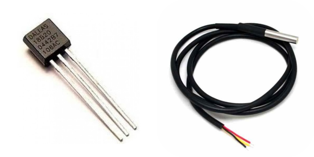
I use either the I2C BME280 environmental sensor or the DS18B20 digital temperature sensor to monitor temperature in all of my applications. The DS18B20 comes in several packages, the most commonly used two being TO-92 (at left in the above photo), which can be mounted directly on a circuit board, and a waterproof, stainless steel package (at right int he above photo), on leads of various lengths, that can be mounted remotely. The TO-92 configuration is included as an option on all of my base PCBs.
Configuration
There are plenty of posts on the Web on the configuration of DS18B20 digital temperature sensors. The only thing that's not discussed widely is the need to be careful with the version of the OneWire library that is used when working with different processors. I'll fill this section out in due course just for completeness but, in the interim, note the comment in the Software section below on the OneWire library, particularly if compiling code for both ESP32 and ASR650x processors.
Links to relevant resources:
- DS18B20 Datasheet
- Overview of 1-Wire Technology and Its Use
- Guidelines for Reliable Long Line 1-Wire Networks
- Forum discussion on connecting multiple long-line DS18B20 sensors
- Forum discussion on inclusion of a decoupling capacitor
Hardware
The DS18B20 communicates over a 1-Wire bus. Each DS18B20 has a unique 64-bit address, allowing multiple DS18B20s to function on the same 1-Wire bus.
The typical DS18B20 configuration includes two additional components, apart from the sensor itself—a pull-up resistor (see note below in relation to configurations that include long cables) and, in some configurations, a filter capacitor to help minimise interference and improve signal quality. Various discussions on the subject suggest that the resistor should be configured as close as possible to the processor and the capacitor as close as possible to the sensor, recognising that the latter may be difficult, or simply not possible, in the case of the waterproof sensor on a long lead.
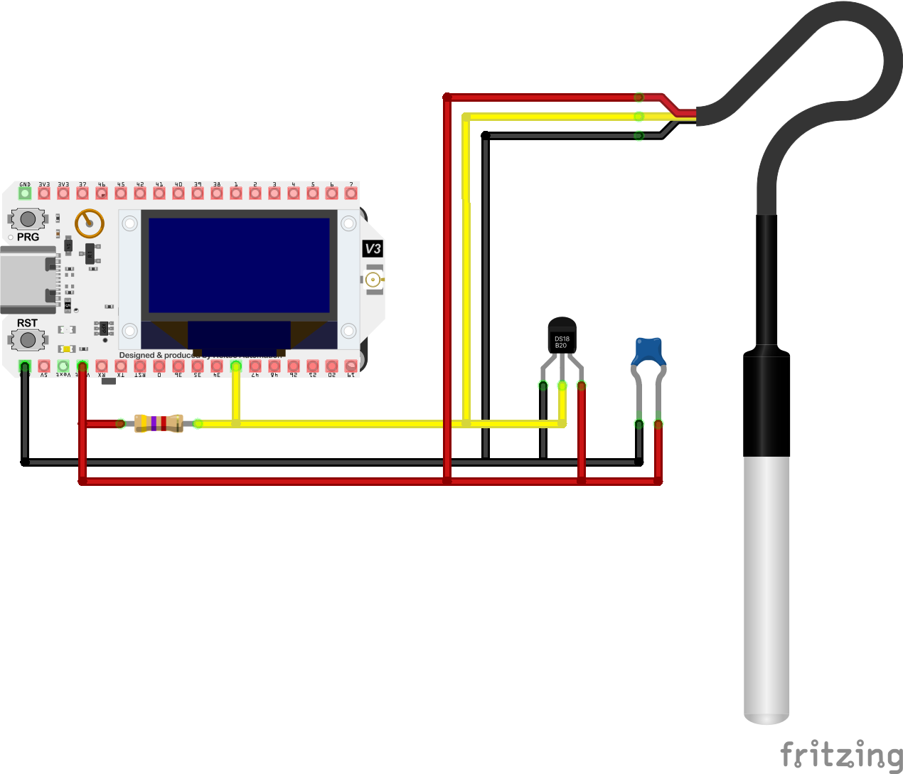
WiFi LoRa 32 (V3) / DS18B20 Electrical Circuit
Pin Configuration
| WiFi LoRa 32 (V3) | DS18B20 | GND | GND |
|---|---|
| GPIO33 | DQ |
| Vext | VDD |
Summary of configuration recommendations derived from the resources listed above:
- When using multiple sensors, connect them in parallel
- Ensure cables on multiple sensors are of similar length
- If all cable lengths are not similar, use multiple sets of [one or more] sensors, grouping sensors with similar length cables
- If using multiple sensor sets, connect each to a separate data pin on the controlling MCU—each set of sensors (data pin) should then be configured on an individual 1-Wire bus instance
- Ensure that a pull-up resistor is configured on the data line of the, or on each data line if there is more than one, 1-Wire bus. A 4k7Ω resistor is generally recommended and is OK for a single sensor or sensors on relatively short cables. For longer cable runs, and 20 metres or more appears not to be unusual, a resistor of smaller value (2k2Ω or even 1kΩ) will be required
- A decoupling capacitor can be added between the power supply lines, although this may be of limited benefit if it cannot be configured close to the sensor itself
- A 100Ω resistor can be added in-line, on the data line, to improve signal quality
Further details pending
TO-92 IC
Details
Stainless Steel Probe
At one point I had need of a probe on a cable 3-4m long—up to this point I had only used shorter cables (<1m). For the moment, I will just note that, in my experience (and there are various threads on relevant forums that discuss this issue— see links above) the 4k7Ω pull-up resistor that is generally specified in my PCB designs needs to be replaced by a 2k2Ω resistor for this to work. This apparently has to do with the ramp-up time for signal transmission on the OneWire bus.
Further details pending
Software
Update the following to read two sensors, as per the above illustration, noting what is required if only a single sensor is being read, and just write the results to the Serial Monitor
|
Alternative base code... (Utilities/DS18B20Test.ino)
|
OneWire Library Compatibility
I generally use the Paul Stoffregen OneWire library (OneWire.h) and the Miles Burton DallasTemperature library (DallasTemperature.h), both of which are available via the Library Manager within the Arduino IDE.
The CubeCell software support files, however, include their own version of the OneWire library that differs slightly from the one that is loaded through the Arduino IDE Library Manager. I may just be doing something wrong, but the version in the main library folder seems to always take precedence over the CubeCell version, which is buried down in the CubeCell hardware directory.
Unfortunately, the default version doesn't work with the CubeCell platform—sketches compile, but always return a value of -127—and the CubeCell version doesn't work with other platforms, in my case that's primarily the ESP32, where sketches won't even compile with the CubeCell version of the library. To rectify this situation, the 'standard' library file [OneWire.cpp] needs to be modified as follows (Note: Actual line numbers may change with more recent revisions of the library).
Three occurrences (lines 167, 201 & 229) of:
|
__attribute__((unused)) volatile IO_REG_TYPE *reg IO_REG_BASE_ATTR = baseReg; |
need to be replaced by
|
#if defined(__ASR_Arduino__) volatile IO_REG_TYPE *reg IO_REG_BASE_ATTR = baseReg; #else __attribute__((unused)) volatile IO_REG_TYPE *reg IO_REG_BASE_ATTR = baseReg; #endif |
In addition to the above, the two files in the util directory, OneWire_direct_gpio.h and OneWire_direct_regtype.h also need to be modified to include code to support the ASR processors in the CubeCell dev-boards.
In the file OneWire_direct_gpio.h, replace line 261
|
#elif defined(__ASR6501__) |
with
|
#elif defined(__asr650x__) |
lines 267–268
|
#define PIN_TO_BASEREG(pin)(0) #define PIN_TO_BITMASK(pin)(pin) |
with
|
#define PIN_TO_BASEREG(pin)(uint32_t *)PORT_ADDRESS(pin) #define PIN_TO_BITMASK(pin)PIN_IN_PORT(pin) |
lines 272–276
|
#define DIRECT_READ(base, pin)CY_SYS_PINS_READ_PIN(PORT_ADDRESS(pin)+4, PIN_IN_PORT(pin)) #define DIRECT_WRITE_LOW(base, pin)CY_SYS_PINS_CLEAR_PIN(PORT_ADDRESS(pin), PIN_IN_PORT(pin)) #define DIRECT_WRITE_HIGH(base, pin)CY_SYS_PINS_SET_PIN(PORT_ADDRESS(pin), PIN_IN_PORT(pin)) #define DIRECT_MODE_INPUT(base, pin)CY_SYS_PINS_SET_DRIVE_MODE(PORT_ADDRESS(pin)+8, PIN_IN_PORT(pin), CY_SYS_PINS_DM_DIG_HIZ) #define DIRECT_MODE_OUTPUT(base, pin)CY_SYS_PINS_SET_DRIVE_MODE(PORT_ADDRESS(pin)+8, PIN_IN_PORT(pin), CY_SYS_PINS_DM_STRONG) |
with
|
#define DIRECT_READ(base, pin)CY_SYS_PINS_READ_PIN((uint32_t)base+4, pin) #define DIRECT_WRITE_LOW(base, pin)CY_SYS_PINS_CLEAR_PIN((uint32_t)base, pin) #define DIRECT_WRITE_HIGH(base, pin)CY_SYS_PINS_SET_PIN((uint32_t)base, pin) #define DIRECT_MODE_INPUT(base, pin)CY_SYS_PINS_SET_DRIVE_MODE((uint32_t)base+8, pin, CY_SYS_PINS_DM_DIG_HIZ) #define DIRECT_MODE_OUTPUT(base, pin)CY_SYS_PINS_SET_DRIVE_MODE((uint32_t)base+8, pin, CY_SYS_PINS_DM_STRONG) |
and at line 277, insert the lines
|
#elif defined(__asr6601__) #define PIN_IN_PORT(pin)(pin % PIN_NUMBER_IN_PORT) #define PORT_FROM_PIN(pin)(pin / PIN_NUMBER_IN_PORT) #define PORT_OFFSET(port)(PORT_REG_SHFIT * port) #define PORT_ADDRESS(pin)(0x4001F000 + PORT_OFFSET(PORT_FROM_PIN(pin))) #define PIN_TO_BASEREG(pin)(uint32_t *)PORT_ADDRESS(pin) #define PIN_TO_BITMASK(pin)PIN_IN_PORT(pin) #define IO_REG_TYPE uint32_t #define IO_REG_BASE_ATTR #define IO_REG_MASK_ATTR #define DIRECT_READ(base, pin)gpio_read((gpio_t*)base, pin) #define DIRECT_WRITE_LOW(base, pin)gpio_write((gpio_t*)base, pin, GPIO_LEVEL_LOW) #define DIRECT_WRITE_HIGH(base, pin)gpio_write((gpio_t*)base, pin, GPIO_LEVEL_HIGH) #define DIRECT_MODE_INPUT(base, pin)gpio_init((gpio_t*)base, pin, GPIO_MODE_INPUT_FLOATING) #define DIRECT_MODE_OUTPUT(base, pin)gpio_init((gpio_t*)base, pin, GPIO_MODE_OUTPUT_PP_LOW) |
In the file OneWire_direct_regtype.h, at line 39,
replace the line
|
#elif defined(__ASR6501__) |
with
|
#elif defined(__asr650x__) |
and at line 41, insert the lines
|
#elif defined(__asr6601__) #define IO_REG_TYPE uint32_t |
If you're not interested in the details, the following is the modified OneWire library that I am currently using with both ESP32 and ASR6502 platforms.

|
OneWire library | 9-Apr-2024 | [30 KB] |
Further details pending