

10068-WS PCB
Board Layout
The various subsystems are identified in the board schematic and laid out as illustrated below:
| Top | Bottom |
|---|---|
 |
 |
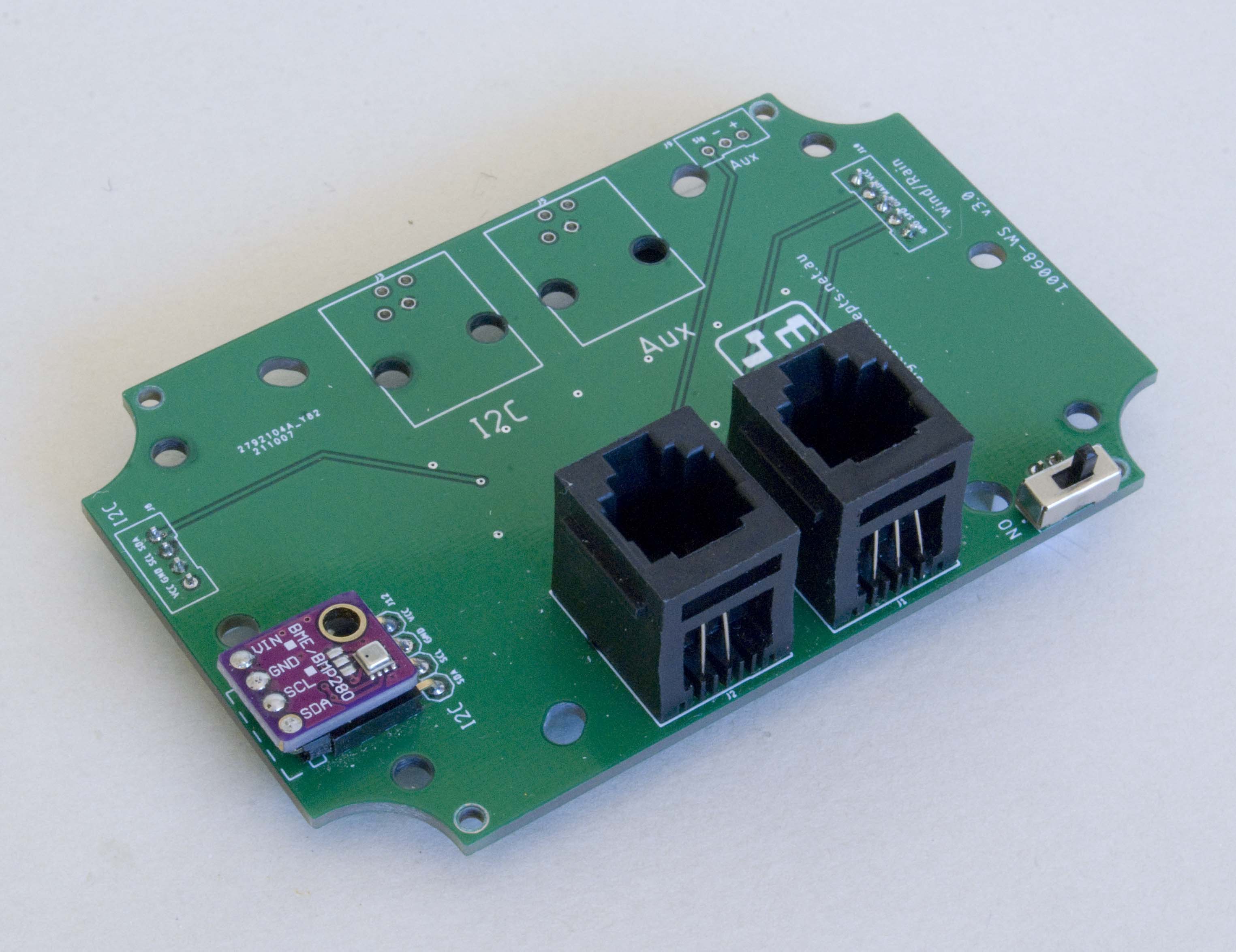
10068-WS [v3.2] PCB
See here for CAD and CAM files.
Configuration
The WS (Weather-Station) board provides connectivity for weather station sensors, primarily the Davis rain collector and anemometer and I2C sensors. It is intended for use with other boards in a 'stack' configuration.
Input Line Over-Current/Over-Voltage Protection
Each of the digital input lines is configured with a basic input protection circuit—a 1kΩ in series resistor to limit the input current and a dual diode arrangement, with a decoupling capacitor, to protect against voltage spikes. A pull-up resistor can also be configured.

Digital Line Input Protection Circuit
The analog circuit that is used to measure wind direction is not configured with the protection circuit resistors as these have a direct impact on the linearity of the input from the Davis anemometer trimpot. As such, there is no over-current protection on this circuit.
Some background information on line protection is provided in this article. and I drew the configuration of my circuits from here (I used 1N5819 diodes rather then 1N5818s simply because I had the former at hand).
Board Stacking
The 10068-WS board is designed to be used in a 'stack' configuration with an appropriate processor board.

10068-WS PCB in Weather Station Node Board Stack
Further details pending