

DS1307 Real Time Clock Module
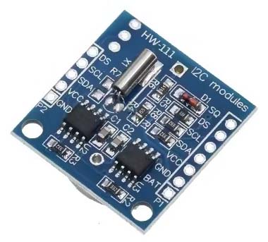
This section deals with the DS1307 real time clock module that can be used in applications where accurate time measurement is required.
Application
TBA
Configuration
No point reinventing the wheel here, see Last Minute Engineers for details.
The module does not appear to store any configuration information until a [CR2032] battery has been installed in the onboard battery holder.
Hardware
The DS1307 real time clock module is configured on an I2C bus, with a 3.3V supply voltage. The module includes an AT24C32 EEPROM, which is also connected to the I2C bus. As a result, there are two independently I2C addressable entities present: the DS1307 at address 0x68 and the EEPROM at address 0x50. Unfortunately, the latter is the same I2C address that is used by default by the EEPROM on the processor boards described elsewhere on this website (capacity notwithstanding, the two EEPROMs are, after all, identical). When the two must used in the same application, one will need to have its default address overridden or the EERPOM can simply be omitted from the processor board and any relevant information stored on the RTC module EEPROM.
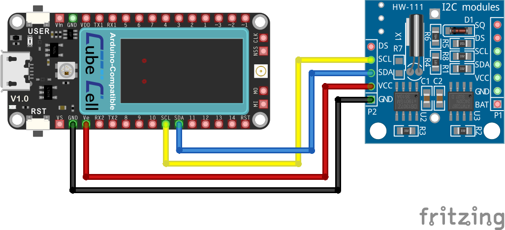
CubeCell Plus - DS1307 Electrical Circuit
Pin Configuration
| CubeCell Plus | DS1307 |
|---|---|
| Vext | VCC |
| GND | GND |
| SCL | SCL |
| SDA | SDA |
Software
For no particular reason, I have used the Adafruit RTClib DS1307 library, available through the Library Manager under the Arduino IDE, and, for the time being, my own EepromHandler library to manage the content of the onboard EEPROM.
Once I installed a battery and set the time, the example sketches provided with the Adafruit library executed as expected.
|
Further details pending