

OLED Display
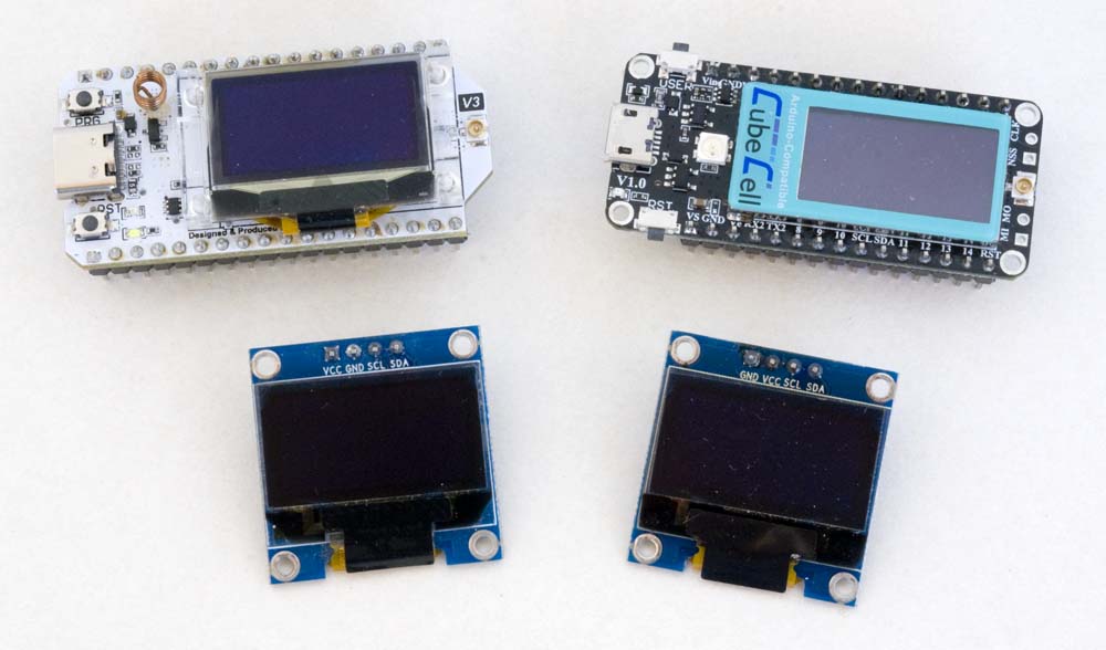
While the processor modules most often used in my projects, the Heltec WiFi LoRa 32 and CubeCell Plus, incorporate an onboard display, an 'external' display can be configured on any of the processor modules I have used. While I have played around with larger displays, the one I have used most often is the SSD1306 (or SSD1306-compatible) 128×64 OLED I2C display.
As an I2C device, there is essentially no difference between the configuration of an internal or external display, although there are a couple of potential issues that may need to be considered.
One characteristic of these displays that I will point out at the outset is that pixels burn out, over a period of a year or so, if they are constantly on. This is not as big a problem if the screen content changes frequently, but if the same or a similar message is displayed in the same location for an extended period, those pixels will effectively die. Having experienced this problem first hand, in most of my applications I now turn the display off automatically after a short period and provide an interrupt button that, when pressed, reactivates the display for that same short period before again turning off.
Configuration
While the subject display is available with either an I2C or SPI interface, I have only ever used the I2C version.
Hardware
There is still a minor complication here in that these displays may be supplied in two different pin configurations, as illustrated below.
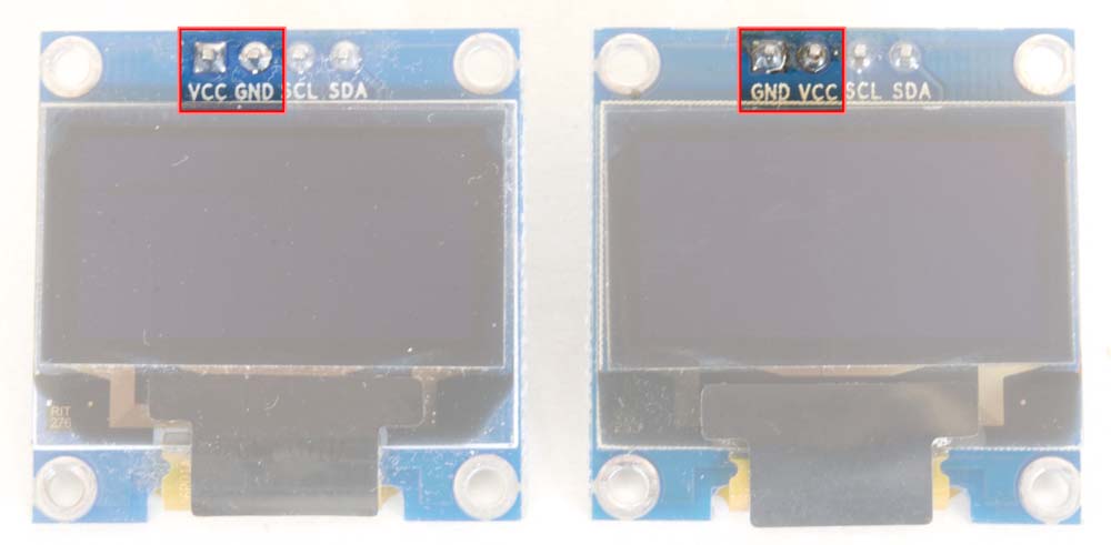
OLED Display Pin Configurations
As a result, it's important to ensure that the required pin configuration is specified or verified when making a purchase. This problem can be circumvented to some extent by using an appropriate adaptor board, if that option is available and practical.
I 2C Address
The external SSD1306 OLED displays in the present illustrations use a [7‑bit] I2C address of 0x3C or 0x3D. When written on an I2C bus to identify the recipient device, however, the binary value, 0111100 or 0111101 respectively, is written as the left-most 7 bits in an 8‑bit byte, 0111 1000 or 0111 1010 respectively, with the state of the least significant bit (LSB), or right-most bit, used to indicate whether the subsequent operation is a read (1) or write (0). This leads to the sometimes confusing situation when the I2C address is presented as it would be stored in an 8‑bit byte, 0x78 or 0x7A respectively in the present case.
This is relevant in the present context because, while an I2C scanner will report an address of 0x3C or 0x3D for the OLED displays, the silkscreen on the OLED display modules themselves, as illustrated below, shows the 8‑bit 0x78 / 0x7A representations.
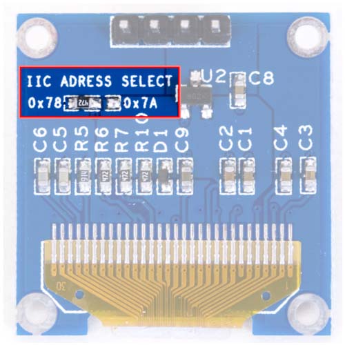
OLED Display I2C Address Selection
The default 0x3C I2C address on the OLED display illustrated above can be changed to 0x3D by moving the jumper resistor from the left-most (0x78) to the right-most (0x7A) pair of pads.
While the Heltec WiFi LoRa 32 module effectively uses the same SSD1306 display element as the external OLED display module, the CubeCell Plus board uses an SH1107 display. Both, however, use the same, fixed 0x3C I2C address.
Software
OLED Display Libraries
There are any number of libraries available that support SSD1306 and compatible displays and, while Heltec example sketches generally use a specific Heltec library, HT_SSD1306Wire, I have always used the ThingPulse SSD1306 library, available through the Arduino IDE Library Manager, whether for an onboard Heltec [WiFi LoRa 32] display or an external OLED display. For the SH1107 display on the CubeCell Plus board, however, I have always used the Heltec HT_SH1107Wire library, which is included as part of the Heltec CubeCell software support environment.
Once the constructors have been defined, the basic usage of each of the aforementioned libraries is essentially the same, as illustrated in the following sketch extracts.
|
Different libraries do, nonetheless, often include additional functions, particularly graphics functions, which may or may not provide a benefit in a given situation. In my applications, I am only ever writing text to the display, so this has not been an issue for me.
In this regard, it should be noted that three font sizes are included in the libraries by default (others can apparently be used if the relevant font description files are available)—ArialMT_Plain_10, ArialMT_Plain_16 and ArialMT_Plain_24 (the number seems to indicate the respective line heights).
For what it's worth, testing the bounds of the display with the different font sizes also seemed to indicate that the addressable depth of the display is somewhat less than 64 pixels, for the display of text if nothing else. The last Y-coordinate (the Y-coordinate in the drawstring(x,y,string) method is the line of the top of the characters) that can be used to write the 10 font without clipping off the bottom is 52 (not 54) and for the 16 font is 46 (not 48), which would seem to indicate that the display is clipping past the 62nd pixel. Curiously, the last Y-coordinate that can be used to write the 24 font without clipping is 37 (not 40), which would seem to indicate that, in this case, the display is clipping past the 61st pixel. There's probably a perfectly reasonable explanation for these observations, but I am yet to discover it.
Using Two OLED Displays
There are two ways to configure two I2C OLED displays on a single processor module. The first is to configure distinct I2C addresses on the two displays (a function of the individual display module hardware configuration as discussed above) and connect them to a single I2C bus. The second is to configure the two displays on two distinct I2C buses, the only option available if the two display modules cannot conveniently be configured with different I2C addresses.
|
|
Using Two Constructors for a Single OLED Display
This may be a bit of an esoteric issue, but it is also possible to drive a single display through multiple constructors, which need not even be using the same software support library. This can be an important consideration when using certain Heltec libraries (e.g. the Heltec LoRaWan_APP library) because, for reasons best known to themselves, Heltec defined and used the onboard display on relevant boards inside completely unrelated libraries. For the user to then use the onboard display in these situations, the user still needs to declare their own instance of the display constructor but remain aware of the fact that they are actually sharing control of the target resource.
This issue is discussed in more detail on the I2C Software page.