WeAct 1.54" ePaper Module
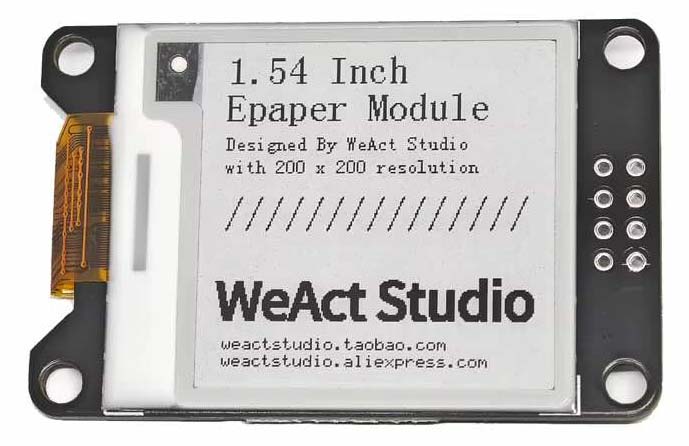
This section provides details of the configuration of a WeAct Studio 1.54" ePaper display module on the SPI bus of several different processors that I have used in IoT Node configurations.
Hardware Configuration
The hardware configurations used for the WeAct ePaper display module with the platforms tested are as illustrated below.
NodeMCU [ESP8266]
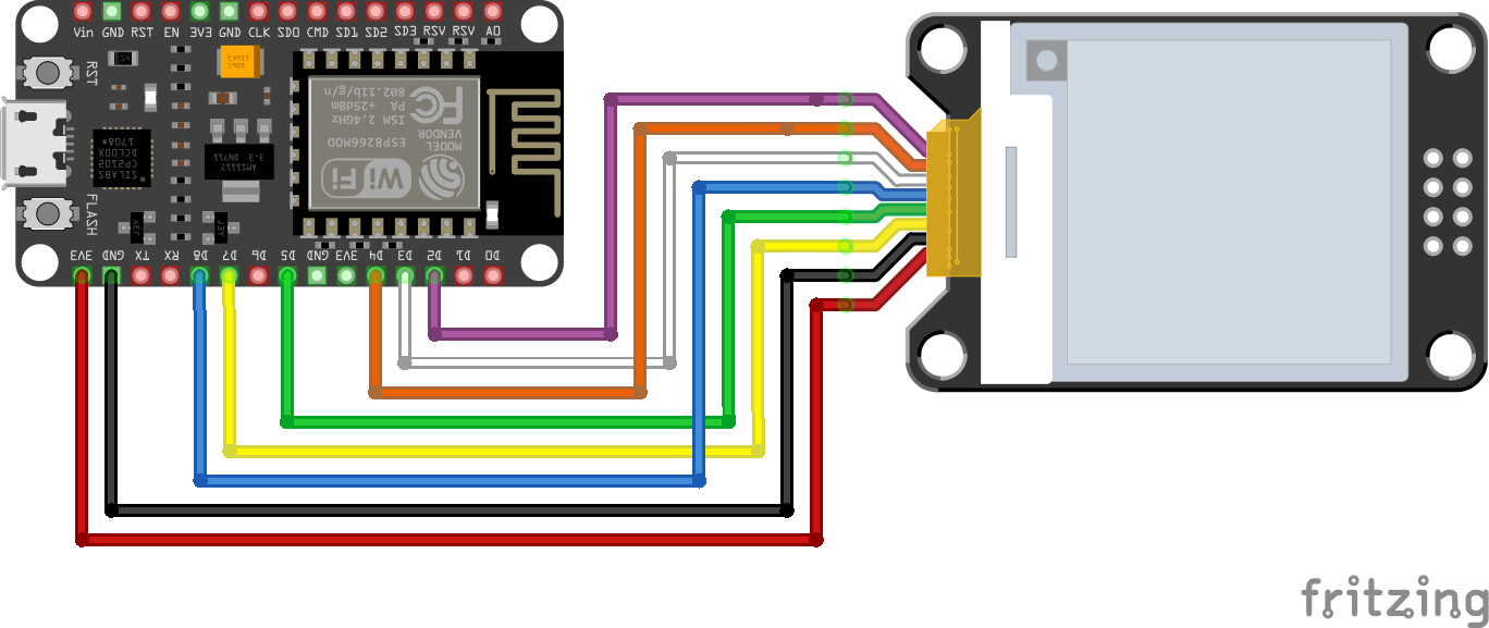
NodeMCU - WeAct ePaper Module Electrical Circuit
Wireless Stick Lite V3 [ESP32-S3]
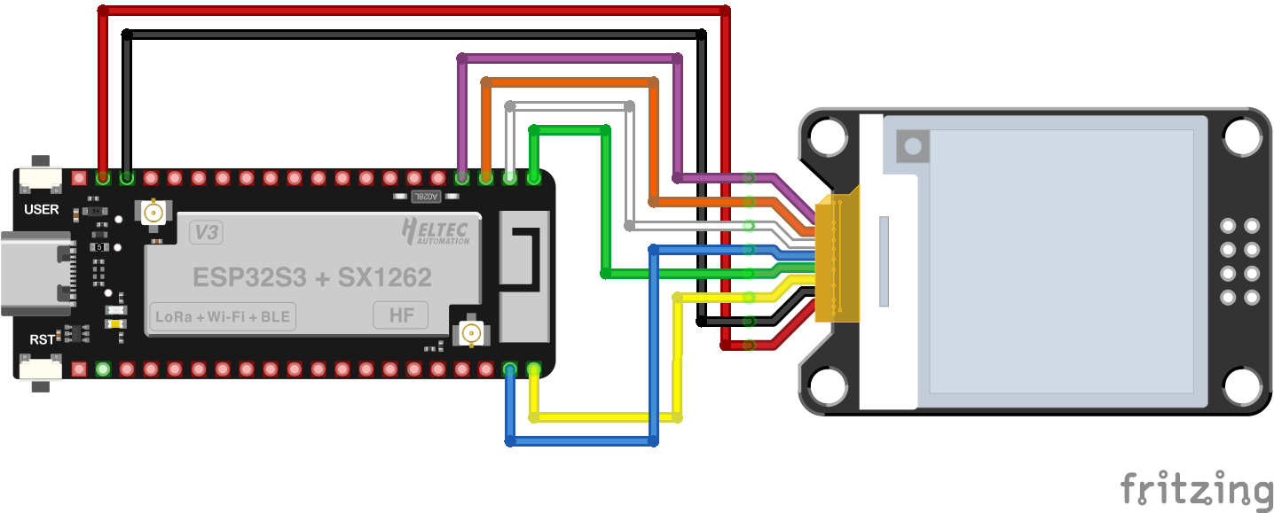
Wireless Stick Lite V3 - WeAct ePaper Module Electrical Circuit
CubeCell [ASR650x]
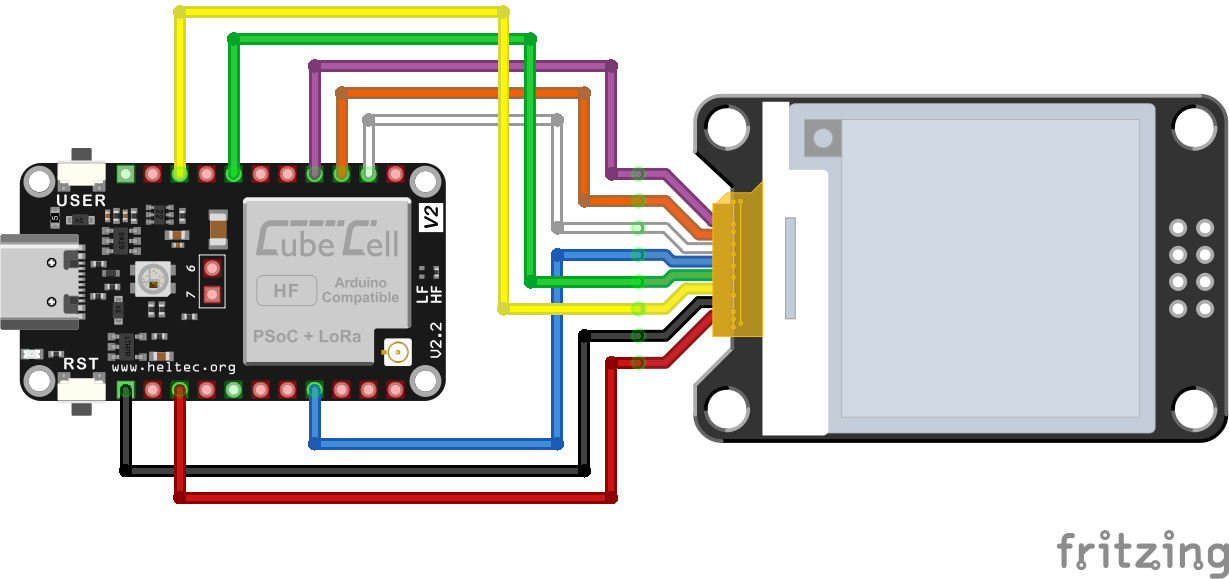
CubeCell - WeAct ePaper Module Electrical Circuit
Pin Configurations
| NodeMCU |
Wireless Stick Lite V3 |
CubeCell |
ePaper Display (SPI) |
| 3V3 |
3V3 |
3V3 |
VCC |
| GND |
GND |
GND |
GND |
| D7 |
GPIO3 |
MOSI |
SCA |
| D5 |
GPIO4 |
SCK |
SCL |
| D8 |
GPIO2 |
GPIO0 |
CS |
| D3 |
GPIO5 |
GPIO1 |
D/C |
| D4 |
GPIO6 |
GPIO2 |
RES |
| D2 |
GPIO7 |
GPIO3 |
BUSY |
Software
To date, I've just run a test sketch using the [Jean-Marc Zingg] GxEPD2 library to verify the above hardware configurations and to work out the basic software configuration requirements. This library can be loaded through the Arduino Library Manager and includes several example sketches. The following tests are based on the GxEPD2_Example.ino example sketch.
NodeMCU
In the case of the NodeMCU platform, the recommended pin configuration is as illustrated above and the only modification to the example sketch that is required is to uncomment the display module constructor specification at line 23 of the GxEPD2_display_selection.h file that is loaded with the sketch:
GxEPD2_BW<GxEPD2_154_D67, GxEPD2_154_D67::HEIGHT> display(GxEPD2_154_D67(/*CS=D8*/ SS, /*DC=D3*/ 0, /*RST=D4*/ 2, /*BUSY=D2*/ 4)); // GDEH0154D67 200x200, SSD1681
|
The resulting sketch then compiles, loads and executes without any apparent issues. Without necessarily knowing what is supposed to happen, the sketch seems to load and run OK, displaying the usual range of text and graphics to illustrate the capabilities of the display module.
Wireless Stick Lite V3
The GxEPD2 library includes configuration options for several processor platforms (ESP8266, ESP32, AVR, STM32) and a wide range of display modules. Unfortunately, this complicates the presentation of the example sketches, which include literally dozens of alternative configurations that must be chosen between for a given platform configuration. This wasn't such a problem in the NodeMCU case where it was just a case of identifying the appropriate constructor for our display module. For other platforms, there are more choices to make and more optional code to sift through.
In the case of the Wireless Stick Lite V3 platform, the main issue is the need to define and use the second SPI bus, SPI1, since the first SPI bus is dedicated to servicing the LoRa chip, through pins that are not broken out for general use.
The basic display module constructor is the same as that used in the NodeMCU configuration, with the pin identifiers set to reflect those used for the Wireless Stick Lite V3 MCU.
Accordingly, to configure the example sketch for use with the Wireless Stick Lite V3 platform, lines 47~190 of the GxEPD2_Example.ino example sketch:
// select the display constructor line in one of the following files (old style):
#include "GxEPD2_display_selection.h"
#include "GxEPD2_display_selection_added.h"

// or select the display class and display driver class in the following file (new style):
#include "GxEPD2_display_selection_new_style.h"

//#define WITHOUT_BITMAPS
#ifndef WITHOUT_BITMAPS

#if !defined(__AVR) && !defined(STM32F1xx)

// note 16.11.2019: the compiler may exclude code based on constant if statements (display.epd2.panel == constant),
//                  therefore bitmaps may get optimized out by the linker

// comment out unused bitmaps to reduce code space used
#include "bitmaps/Bitmaps80x128.h"  // 1.02" b/w
#include "bitmaps/Bitmaps152x152.h" // 1.54" b/w
#include "bitmaps/Bitmaps200x200.h" // 1.54" b/w
#include "bitmaps/Bitmaps104x212.h" // 2.13" b/w flexible GDEW0213I5F
#include "bitmaps/Bitmaps128x250.h" // 2.13" b/w
#include "bitmaps/Bitmaps128x296.h" // 2.9"  b/w
#include "bitmaps/Bitmaps168x384.h" // 2.9"  b/w
#include "bitmaps/Bitmaps152x296.h" // 2.6"  b/w
#include "bitmaps/Bitmaps176x264.h" // 2.7"  b/w
#include "bitmaps/Bitmaps240x360.h" // 3.1" b/w
#include "bitmaps/Bitmaps240x416.h" // 3.71"  b/w
#include "bitmaps/Bitmaps400x300.h" // 4.2"  b/w
#include "bitmaps/Bitmaps648x480.h" // 5.38"  b/w
#include "bitmaps/Bitmaps640x384.h" // 7.5"  b/w
#include "bitmaps/Bitmaps800x276.h" // 5.79" b/w
#include "bitmaps/Bitmaps800x480.h" // 7.5"  b/w
#include "bitmaps/Bitmaps960x640.h" // 10.2"  b/w
#include "bitmaps/Bitmaps960x680.h" // 13.3"  b/w
// 3-color
#include "bitmaps/Bitmaps3c200x200.h" // 1.54" b/w/r
#include "bitmaps/Bitmaps3c104x212.h" // 2.13" b/w/r
#include "bitmaps/Bitmaps3c128x250.h" // 2.13" b/w/r
#include "bitmaps/Bitmaps3c128x296.h" // 2.9"  b/w/r
#include "bitmaps/Bitmaps3c152x296.h" // 2.66" b/w/r
#include "bitmaps/Bitmaps3c176x264.h" // 2.7"  b/w/r
#include "bitmaps/Bitmaps3c400x300.h" // 4.2"  b/w/r
#if defined(ESP8266) || defined(ESP32) || defined(ARDUINO_ARCH_RP2040)
#include "bitmaps/Bitmaps3c800x276.h" // 5.79" b/w/r
#include "bitmaps/Bitmaps3c648x480.h" // 5.83" b/w/r
#include "bitmaps/Bitmaps3c800x480.h" // 7.5"  b/w/r
#include "bitmaps/Bitmaps3c880x528.h" // 7.5"  b/w/r
#include "bitmaps/Bitmaps3c960x640.h" // 11.6" b/w/r
#include "bitmaps/Bitmaps3c960x680.h" // 13.3" b/w/r
#include "bitmaps/WS_Bitmaps800x600.h" // 6.0"  grey
// 4-color
#include "bitmaps/Bitmaps4c128x250.h" // 2.13" 4-color
#include "bitmaps/Bitmaps4c184x360.h" // 2.66" 4-color
#include "bitmaps/Bitmaps4c168x384.h" // 2.9" 4-color
#include "bitmaps/WS_Bitmaps4c168x168.h" // 4.37" 4-color
#include "bitmaps/WS_Bitmaps4c168x400.h" // 3.00" 4-color
#include "bitmaps/Bitmaps4c400x300.h" // 4.2" 4-color
#include "bitmaps/Bitmaps4c792x272.h" // 5.79" 4-color
#include "bitmaps/Bitmaps4c960x640.h" // 11.6" 4-color
// 7-color
#include "bitmaps/Bitmaps7c600x448.h" // 5.65" 7-color
#include "bitmaps/WS_Bitmaps7c192x143.h" // 5.65" 7-color
#include "bitmaps/WS_Bitmaps7c300x180.h" // 7.3" 7-color
#endif
#if defined(ESP32) || defined(ARDUINO_ARCH_RP2040)
#include "bitmaps/Bitmaps1304x984.h" // 12.48" b/w
#include "bitmaps/Bitmaps1360x480.h" // 10.85" b/w
#include "bitmaps/Bitmaps3c1304x984.h" // 12.48" b/w/r
#include "bitmaps/Bitmaps7c800x480.h" // 7.3" 7-color
#endif

#else

// select only one to fit in code space
//#include "bitmaps/Bitmaps80x128.h"  // 1.02" b/w
#include "bitmaps/Bitmaps200x200.h" // 1.54" b/w
//#include "bitmaps/Bitmaps104x212.h" // 2.13" b/w flexible GDEW0213I5F
//#include "bitmaps/Bitmaps128x250.h" // 2.13" b/w
//#include "bitmaps/Bitmaps128x296.h" // 2.9"  b/w
#include "bitmaps/Bitmaps168x384.h" // 2.9"  b/w
//#include "bitmaps/Bitmaps176x264.h" // 2.7"  b/w
////#include "bitmaps/Bitmaps400x300.h" // 4.2"  b/w // not enough code space
////#include "bitmaps/Bitmaps640x384.h" // 7.5"  b/w // not enough code space
////#include "bitmaps/Bitmaps800x480.h" // 7.5"  b/w // not enough code space
// 3-color
//#include "bitmaps/Bitmaps3c200x200.h" // 1.54" b/w/r
//#include "bitmaps/Bitmaps3c104x212.h" // 2.13" b/w/r
#include "bitmaps/Bitmaps3c128x250.h" // 2.13" b/w/r
//#include "bitmaps/Bitmaps3c128x296.h" // 2.9"  b/w/r
//#include "bitmaps/Bitmaps3c176x264.h" // 2.7"  b/w/r
////#include "bitmaps/Bitmaps3c400x300.h" // 4.2"  b/w/r // not enough code space

#endif
#endif

#if defined(ARDUINO_ARCH_RP2040) && (defined(ARDUINO_RASPBERRY_PI_PICO) || defined(ARDUINO_RASPBERRY_PI_PICO_W))
#if defined(__MBED__)
// SPI pins used by GoodDisplay DESPI-PICO. note: steals standard I2C pins PIN_WIRE_SDA (6), PIN_WIRE_SCL (7)
// uncomment next line for use with GoodDisplay DESPI-PICO. // MbedSPI(int miso, int mosi, int sck);
arduino::MbedSPI SPIn(4, 7, 6); // need be valid pins for same SPI channel, else fails blinking 4 long 4 short
// uncomment next line for use with my proto board. // MbedSPI(int miso, int mosi, int sck);
//arduino::MbedSPI SPIn(4, 3, 2); // need be valid pins for same SPI channel, else fails blinking 4 long 4 short
// uncomment next line for use with Waveshare Pico-ePaper-2.9. // MbedSPI(int miso, int mosi, int sck);
// note: doesn't work with Waveshare PhotoPainter, conflict on pin 12. use philhower package instead.
//arduino::MbedSPI SPIn(12, 11, 10); // need be valid pins for same SPI channel, else fails blinking 4 long 4 short
#else // package https://github.com/earlephilhower/arduino-pico
// SPIClassRP2040(spi_inst_t *spi, pin_size_t rx, pin_size_t cs, pin_size_t sck, pin_size_t tx);
// uncomment next line for use with my proto board.
//SPIClassRP2040 SPIn(spi0, 4, 5, 2, 3); // need be valid pins for same SPI channel, else fails blinking 4 long 4 short
// uncomment next line for use with Waveshare Pico-ePaper-2.9 or Waveshare PhotoPainter module
SPIClassRP2040 SPIn(spi1, 12, 13, 10, 11); // need be valid pins for same SPI channel, else fails blinking 4 long 4 short
#endif
#endif

#if defined(ESP32) && defined(USE_HSPI_FOR_EPD)
SPIClass hspi(HSPI);
#endif

void setup()
{
  Serial.begin(115200);
  Serial.println();
  Serial.println("setup");
  delay(100);
#if defined(ARDUINO_ARCH_RP2040) && (defined(ARDUINO_RASPBERRY_PI_PICO) || defined(ARDUINO_RASPBERRY_PI_PICO_W))
  // uncomment next line for use with GoodDisplay DESPI-PICO or my proto board, or Waveshare RPi boards
  display.epd2.selectSPI(SPIn, SPISettings(4000000, MSBFIRST, SPI_MODE0));
  // uncomment next 2 lines to allow recovery from configuration failures
  pinMode(15, INPUT_PULLUP); // safety pin
  while (!digitalRead(15)) delay(100); // check safety pin for fail recovery
  // recovery can be done also by holding BOOTSEL during power-up.
  // uncomment next line for Waveshare PhotoPainter module
  pinMode(16, OUTPUT); digitalWrite(16, HIGH); // power to the paper
#endif
#if defined(ESP32) && defined(USE_HSPI_FOR_EPD)
  hspi.begin(13, 12, 14, 15); // remap hspi for EPD (swap pins)
  display.epd2.selectSPI(hspi, SPISettings(4000000, MSBFIRST, SPI_MODE0));
#elif (defined(ARDUINO_ARCH_ESP32) && defined(ARDUINO_LOLIN_S2_MINI))
  // SPI.begin(sck, miso, mosi, ss); // preset for remapped pins
  SPI.begin(18, -1, 16, 33); // my LOLIN ESP32 S2 mini connection
#endif
  //display.init(115200); // default 10ms reset pulse, e.g. for bare panels with DESPI-C02
  display.init(115200, true, 2, false); // USE THIS for Waveshare boards with "clever" reset circuit, 2ms reset pulse
  //display.init(115200, true, 10, false, SPIn, SPISettings(4000000, MSBFIRST, SPI_MODE0)); // extended init method with SPI channel and/or settings selection
|
should be replaced with the following:
#define MOSI_PIN (3)
#define SCK_PIN (4)
#define CS_PIN (2)
#define BUSY_PIN (7)
#define RES_PIN (6)
#define DC_PIN (5)

// 1.54'' EPD Module
GxEPD2_BW<GxEPD2_154_D67, GxEPD2_154_D67::HEIGHT> display(GxEPD2_154_D67(/*CS=5*/ CS_PIN, /*DC=*/ DC_PIN, /*RES=*/ RES_PIN, /*BUSY=*/ BUSY_PIN)); // GDEH0154D67 200x200, SSD1681

//#define WITHOUT_BITMAPS
#ifndef WITHOUT_BITMAPS

// comment out unused bitmaps to reduce code space used
#include "bitmaps/Bitmaps200x200.h" // 1.54" b/w
#endif

#if defined(ESP32)
SPIClass SPI1;
#endif

void setup()
{
  Serial.begin(115200);
  Serial.println();
  Serial.println("setup");
  delay(100);
#if defined(ESP32)
  SPI1.begin(SCK_PIN, -1, MOSI_PIN, CS_PIN); // remap hspi for EPD (swap pins)
  display.epd2.selectSPI(SPI1, SPISettings(4000000, MSBFIRST, SPI_MODE0));
#endif
  display.init(115200, true, 2, false); // USE THIS for Waveshare boards with "clever" reset circuit, 2ms reset pulse
|
The resulting sketch then compiles, loads and executes as it did on the NodeMCU platform.
CubeCell
There's also a bit more work required with the CubeCell because in this case there are no predefined configuration details identified for CubeCell or ASR processors. Nonetheless, the pin configuration illustrated above seems to work OK. More generally, it was then a case of working through all of the configuration options to determine what might or might not have been relevant in the case fo the CubeCell platform.
To get something that works on that front, start with the GxEPD2_Example.ino example sketch and edit it in a way similar to that undertaken for the Wireless Stick Lite platform. In this case, we don't need anything special on the SPI front, we just need to specify the relevant pin configuration and display module constructor. Accordingly, replace just lines 47~163:
// select the display constructor line in one of the following files (old style):
#include "GxEPD2_display_selection.h"
#include "GxEPD2_display_selection_added.h"

// or select the display class and display driver class in the following file (new style):
#include "GxEPD2_display_selection_new_style.h"

//#define WITHOUT_BITMAPS
#ifndef WITHOUT_BITMAPS

#if !defined(__AVR) && !defined(STM32F1xx)

// note 16.11.2019: the compiler may exclude code based on constant if statements (display.epd2.panel == constant),
//                  therefore bitmaps may get optimized out by the linker

// comment out unused bitmaps to reduce code space used
#include "bitmaps/Bitmaps80x128.h"  // 1.02" b/w
#include "bitmaps/Bitmaps152x152.h" // 1.54" b/w
#include "bitmaps/Bitmaps200x200.h" // 1.54" b/w
#include "bitmaps/Bitmaps104x212.h" // 2.13" b/w flexible GDEW0213I5F
#include "bitmaps/Bitmaps128x250.h" // 2.13" b/w
#include "bitmaps/Bitmaps128x296.h" // 2.9"  b/w
#include "bitmaps/Bitmaps168x384.h" // 2.9"  b/w
#include "bitmaps/Bitmaps152x296.h" // 2.6"  b/w
#include "bitmaps/Bitmaps176x264.h" // 2.7"  b/w
#include "bitmaps/Bitmaps240x360.h" // 3.1" b/w
#include "bitmaps/Bitmaps240x416.h" // 3.71"  b/w
#include "bitmaps/Bitmaps400x300.h" // 4.2"  b/w
#include "bitmaps/Bitmaps648x480.h" // 5.38"  b/w
#include "bitmaps/Bitmaps640x384.h" // 7.5"  b/w
#include "bitmaps/Bitmaps800x276.h" // 5.79" b/w
#include "bitmaps/Bitmaps800x480.h" // 7.5"  b/w
#include "bitmaps/Bitmaps960x640.h" // 10.2"  b/w
#include "bitmaps/Bitmaps960x680.h" // 13.3"  b/w
// 3-color
#include "bitmaps/Bitmaps3c200x200.h" // 1.54" b/w/r
#include "bitmaps/Bitmaps3c104x212.h" // 2.13" b/w/r
#include "bitmaps/Bitmaps3c128x250.h" // 2.13" b/w/r
#include "bitmaps/Bitmaps3c128x296.h" // 2.9"  b/w/r
#include "bitmaps/Bitmaps3c152x296.h" // 2.66" b/w/r
#include "bitmaps/Bitmaps3c176x264.h" // 2.7"  b/w/r
#include "bitmaps/Bitmaps3c400x300.h" // 4.2"  b/w/r
#if defined(ESP8266) || defined(ESP32) || defined(ARDUINO_ARCH_RP2040)
#include "bitmaps/Bitmaps3c800x276.h" // 5.79" b/w/r
#include "bitmaps/Bitmaps3c648x480.h" // 5.83" b/w/r
#include "bitmaps/Bitmaps3c800x480.h" // 7.5"  b/w/r
#include "bitmaps/Bitmaps3c880x528.h" // 7.5"  b/w/r
#include "bitmaps/Bitmaps3c960x640.h" // 11.6" b/w/r
#include "bitmaps/Bitmaps3c960x680.h" // 13.3" b/w/r
#include "bitmaps/WS_Bitmaps800x600.h" // 6.0"  grey
// 4-color
#include "bitmaps/Bitmaps4c128x250.h" // 2.13" 4-color
#include "bitmaps/Bitmaps4c184x360.h" // 2.66" 4-color
#include "bitmaps/Bitmaps4c168x384.h" // 2.9" 4-color
#include "bitmaps/WS_Bitmaps4c168x168.h" // 4.37" 4-color
#include "bitmaps/WS_Bitmaps4c168x400.h" // 3.00" 4-color
#include "bitmaps/Bitmaps4c400x300.h" // 4.2" 4-color
#include "bitmaps/Bitmaps4c792x272.h" // 5.79" 4-color
#include "bitmaps/Bitmaps4c960x640.h" // 11.6" 4-color
// 7-color
#include "bitmaps/Bitmaps7c600x448.h" // 5.65" 7-color
#include "bitmaps/WS_Bitmaps7c192x143.h" // 5.65" 7-color
#include "bitmaps/WS_Bitmaps7c300x180.h" // 7.3" 7-color
#endif
#if defined(ESP32) || defined(ARDUINO_ARCH_RP2040)
#include "bitmaps/Bitmaps1304x984.h" // 12.48" b/w
#include "bitmaps/Bitmaps1360x480.h" // 10.85" b/w
#include "bitmaps/Bitmaps3c1304x984.h" // 12.48" b/w/r
#include "bitmaps/Bitmaps7c800x480.h" // 7.3" 7-color
#endif

#else

// select only one to fit in code space
//#include "bitmaps/Bitmaps80x128.h"  // 1.02" b/w
#include "bitmaps/Bitmaps200x200.h" // 1.54" b/w
//#include "bitmaps/Bitmaps104x212.h" // 2.13" b/w flexible GDEW0213I5F
//#include "bitmaps/Bitmaps128x250.h" // 2.13" b/w
//#include "bitmaps/Bitmaps128x296.h" // 2.9"  b/w
#include "bitmaps/Bitmaps168x384.h" // 2.9"  b/w
//#include "bitmaps/Bitmaps176x264.h" // 2.7"  b/w
////#include "bitmaps/Bitmaps400x300.h" // 4.2"  b/w // not enough code space
////#include "bitmaps/Bitmaps640x384.h" // 7.5"  b/w // not enough code space
////#include "bitmaps/Bitmaps800x480.h" // 7.5"  b/w // not enough code space
// 3-color
//#include "bitmaps/Bitmaps3c200x200.h" // 1.54" b/w/r
//#include "bitmaps/Bitmaps3c104x212.h" // 2.13" b/w/r
#include "bitmaps/Bitmaps3c128x250.h" // 2.13" b/w/r
//#include "bitmaps/Bitmaps3c128x296.h" // 2.9"  b/w/r
//#include "bitmaps/Bitmaps3c176x264.h" // 2.7"  b/w/r
////#include "bitmaps/Bitmaps3c400x300.h" // 4.2"  b/w/r // not enough code space

#endif
#endif

#if defined(ARDUINO_ARCH_RP2040) && (defined(ARDUINO_RASPBERRY_PI_PICO) || defined(ARDUINO_RASPBERRY_PI_PICO_W))
#if defined(__MBED__)
// SPI pins used by GoodDisplay DESPI-PICO. note: steals standard I2C pins PIN_WIRE_SDA (6), PIN_WIRE_SCL (7)
// uncomment next line for use with GoodDisplay DESPI-PICO. // MbedSPI(int miso, int mosi, int sck);
arduino::MbedSPI SPIn(4, 7, 6); // need be valid pins for same SPI channel, else fails blinking 4 long 4 short
// uncomment next line for use with my proto board. // MbedSPI(int miso, int mosi, int sck);
//arduino::MbedSPI SPIn(4, 3, 2); // need be valid pins for same SPI channel, else fails blinking 4 long 4 short
// uncomment next line for use with Waveshare Pico-ePaper-2.9. // MbedSPI(int miso, int mosi, int sck);
// note: doesn't work with Waveshare PhotoPainter, conflict on pin 12. use philhower package instead.
//arduino::MbedSPI SPIn(12, 11, 10); // need be valid pins for same SPI channel, else fails blinking 4 long 4 short
#else // package https://github.com/earlephilhower/arduino-pico
// SPIClassRP2040(spi_inst_t *spi, pin_size_t rx, pin_size_t cs, pin_size_t sck, pin_size_t tx);
// uncomment next line for use with my proto board.
//SPIClassRP2040 SPIn(spi0, 4, 5, 2, 3); // need be valid pins for same SPI channel, else fails blinking 4 long 4 short
// uncomment next line for use with Waveshare Pico-ePaper-2.9 or Waveshare PhotoPainter module
SPIClassRP2040 SPIn(spi1, 12, 13, 10, 11); // need be valid pins for same SPI channel, else fails blinking 4 long 4 short
#endif
#endif

#if defined(ESP32) && defined(USE_HSPI_FOR_EPD)
SPIClass hspi(HSPI);
#endif
|
with the following:
#define CS_PIN (GPIO0)
#define BUSY_PIN (GPIO3)
#define RES_PIN (GPIO2)
#define DC_PIN (GPIO1)

// 1.54'' EPD Module
GxEPD2_BW<GxEPD2_154_D67, GxEPD2_154_D67::HEIGHT> display(GxEPD2_154_D67(/*CS=5*/ CS_PIN, /*DC=*/ DC_PIN, /*RES=*/ RES_PIN, /*BUSY=*/ BUSY_PIN)); // GDEH0154D67 200x200, SSD1681

//#define WITHOUT_BITMAPS
#ifndef WITHOUT_BITMAPS

// comment out unused bitmaps to reduce code space used
#include "bitmaps/Bitmaps200x200.h" // 1.54" b/w
#endif
|
In the present case we also need to edit the content of the remaining bitmap file that is referred to in the above code segment. In the GxEPD2 library directory, Arduino/libraries/GxEPD2/src/bitmaps, edit the Bitmaps200x200.h file and add a test for the ASR_Arduino architecture in the condition statement:
#if defined(ESP8266) || defined(ESP32)
#include <pgmspace.h>
#else
#include <avr/pgmspace.h>
#endif
|
to yield the following:
#if defined(ESP8266) || defined(ESP32) || defined(__ASR_Arduino__)
#include <pgmspace.h>
#else
#include <avr/pgmspace.h>
#endif
|
The resulting sketch then compiles, loads and executes as it did on the NodeMCU and Wireless Stick Lite V3 platforms.

