A4a LoRa Pro Mini PCB
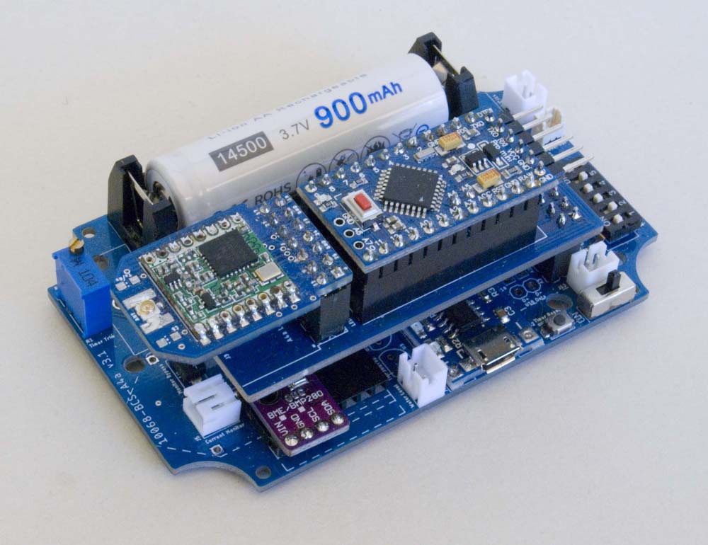
This board is designed to support the Arduino Pro Mini processor module although, as an open hardware platform, there are several variants of the actual implementation. The ones I have used are as illustrated below, available through AliExpress.
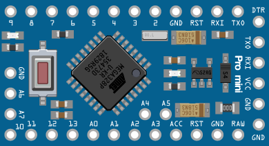
Arduino Pro Mini [35-Pin Variant]
Board Layout
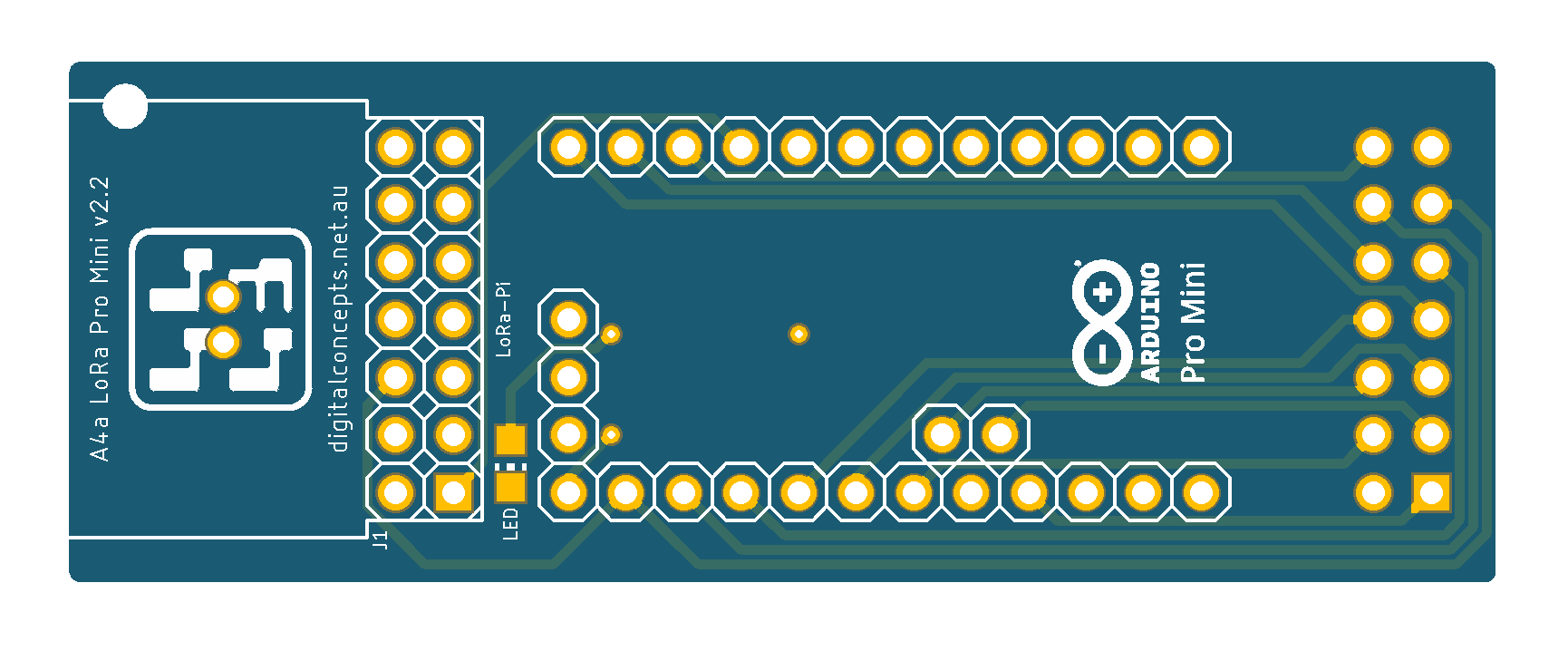
The various elements are identified in the board schematic and laid out as illustrated below:
| Top | Bottom |
|---|---|
 |
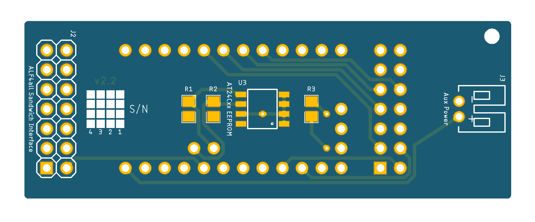 |
A4a LoRa Pro Mini [v2.2] PCB
See here for CAD and CAM files.
Configuration
Basic Configuration
With the obvious exception of the processor itself, almost all of the components on this board are optional. The Arduino Pro Mini module itself includes, for example, the necessary programming interface required to upload software and a voltage regulator.
Processor
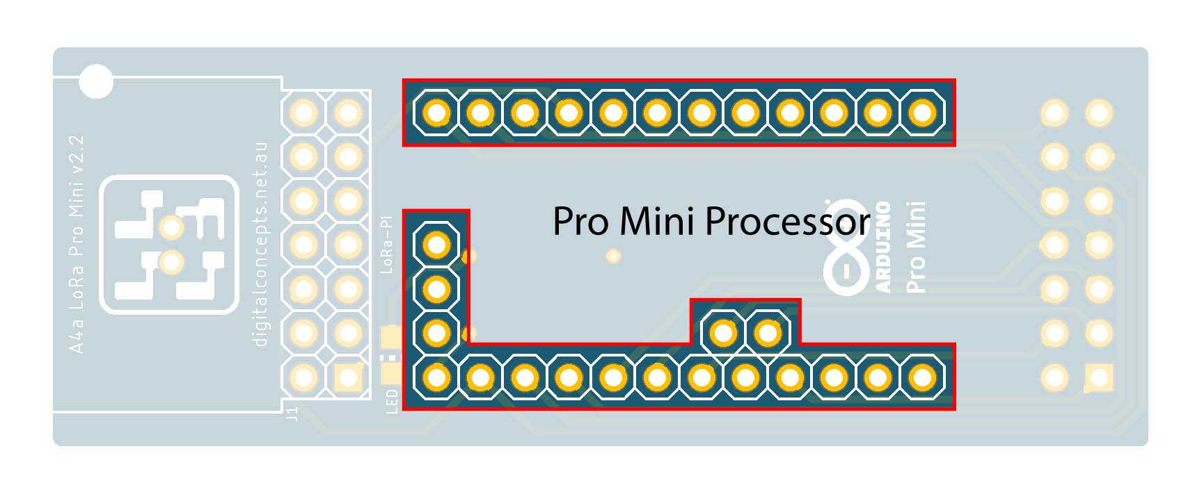
- Two 12 Pin Straight Female Headers
- One 2 Pin Straight Female Header
- One 3 Pin Straight Female Header (not used, so not required)
 |
Arduino Pro Mini Module
Note that, while they are included in the footprint, the three pins at the bottom of the Pro Mini module (GND, A6 & A7) are not used so the associated headers are not actually required.
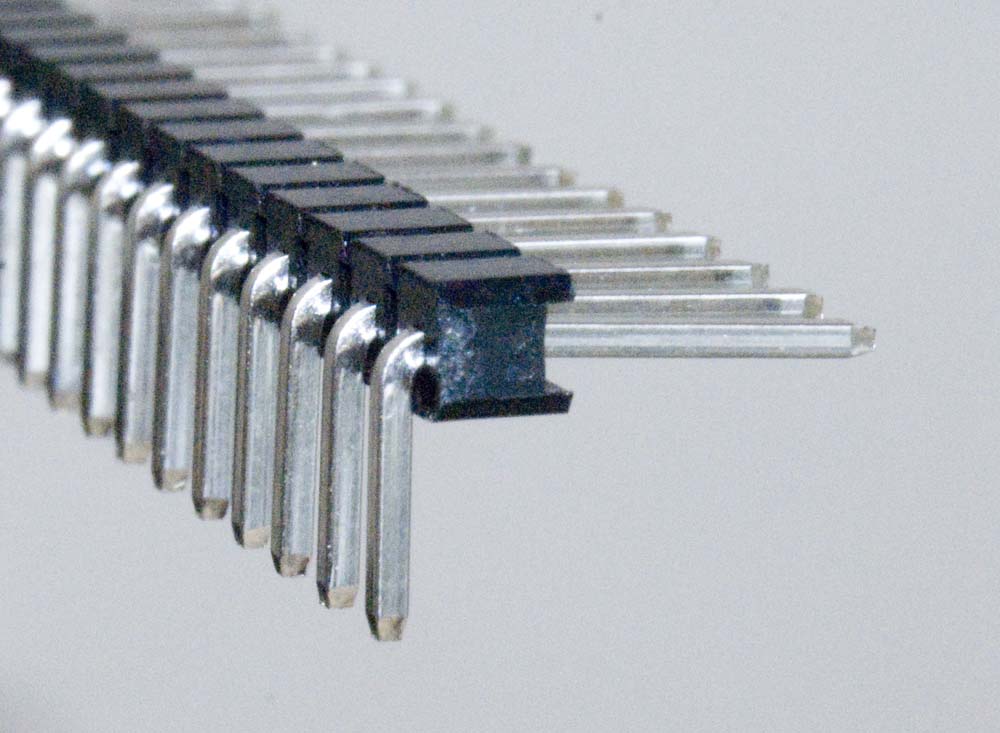
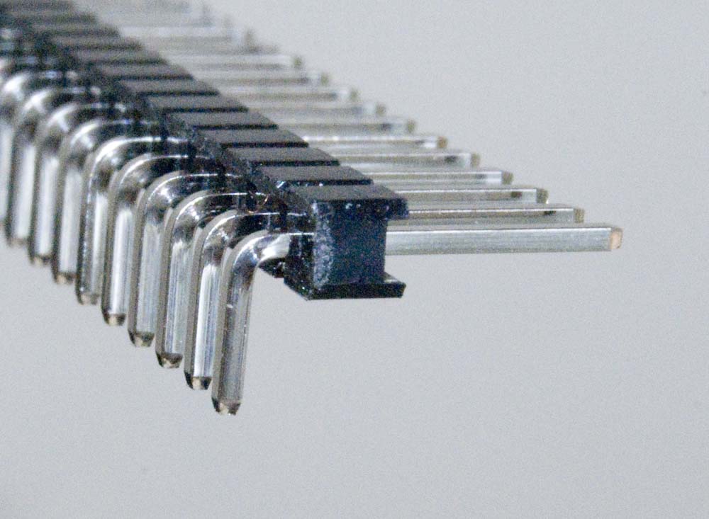
I also use a 'low profile' [male] header for the serial interface of the Pro Mini module, rather than the one provided with the module, to maximise the headroom available within a board stack or enclosure.
| This is the one I generally use | ||
|---|---|---|
 |
 |
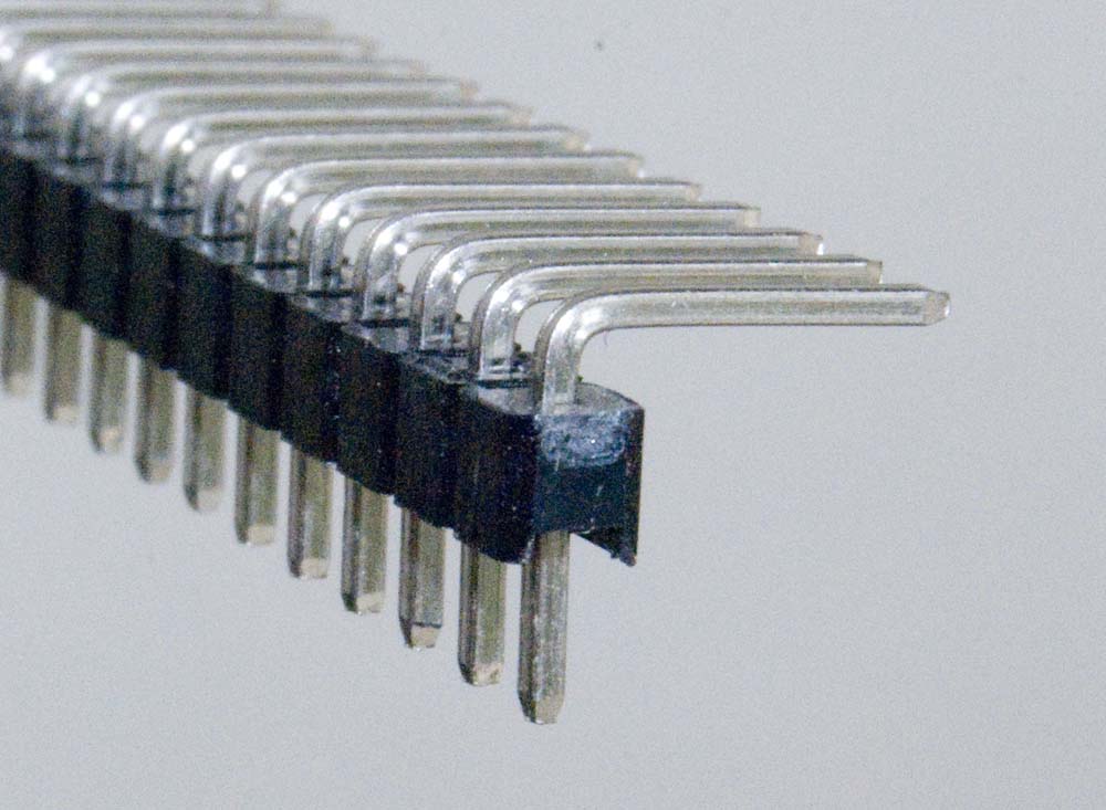 |
Male Right Angle Header Configurations
ALF4all Sandwich Interface Header
- 2×7 Pin Straight Male Header (J2)
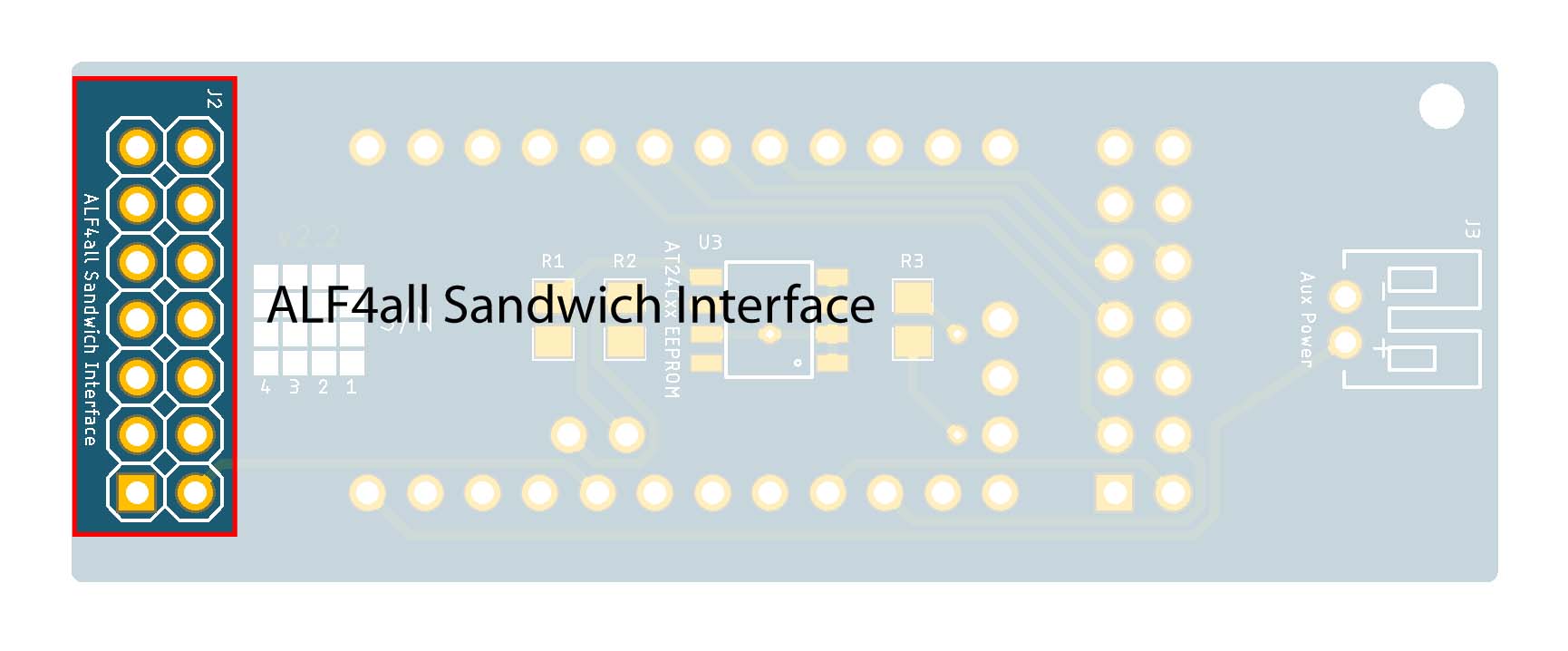 |
ALF4all Sandwich Interface [Male]
All of the A4a processor modules are designed to plug into one of the A4a base boards (8558-BCS-A4a or 10068-BCS-A4a). When configured with one of these power supply/base boards, the processor draws its power from, and connects to relevant sensors through, the base board. These processor modules can, nonetheless, operate independently if they are powered through the auxiliary power connector or, in the case of the NodeMCU board, the onboard USB socket.
Rather than confuse matters by presenting different versions of the A4a Sandwich interface pin configuration that are mirror images of each other, the configuration of the female header on the A4a base boards (e.g. 10068-BCS-A4a) is illustrated below. The configuration of the mating, male header on processor boards is the mirror image of this.
ALF4all Sandwich Interface [Base Board – Female Header] Configuration
Optional Elements
EEPROM
- AT24Cxx (02–64KB) SOP-8 EEPROM (U2)
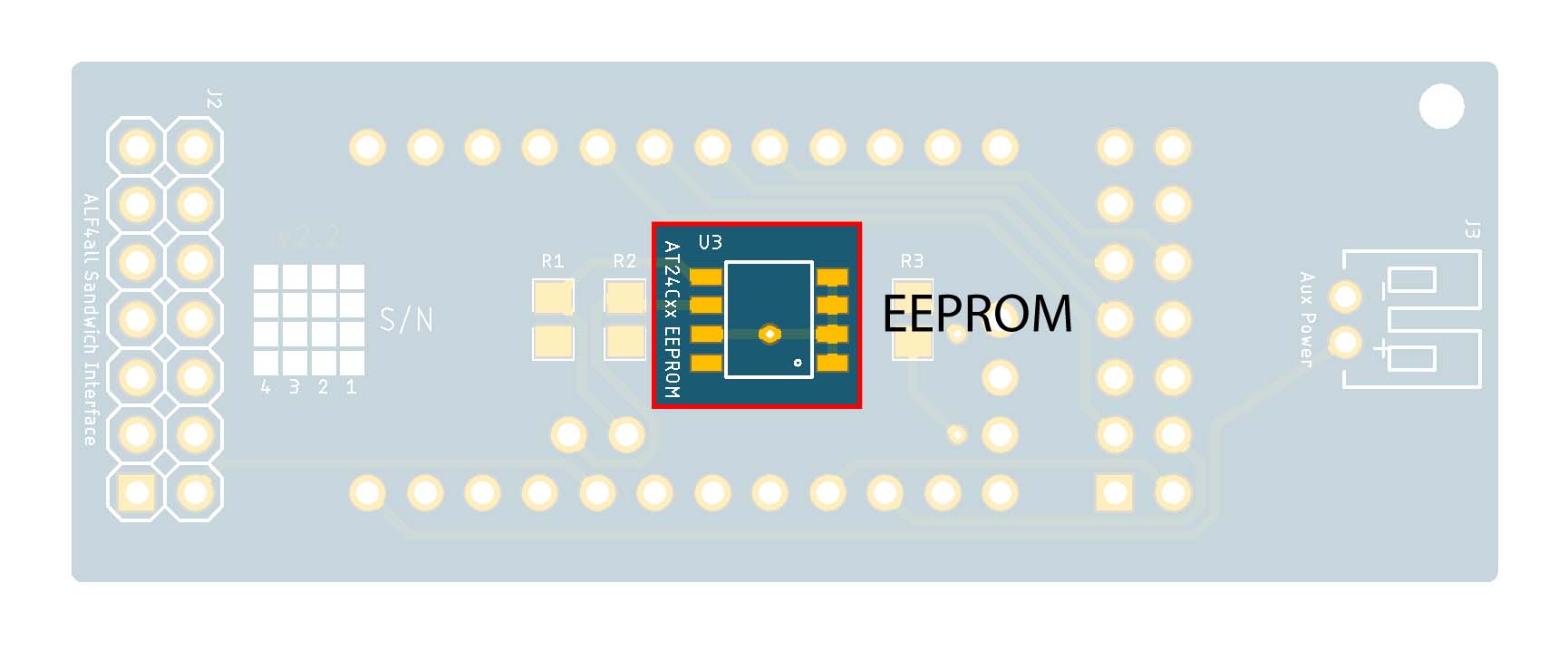 |
EEPROM
Pull-up resistors are generally required on the [SCL/SDA] control lines for the I2C interface when it is configured.
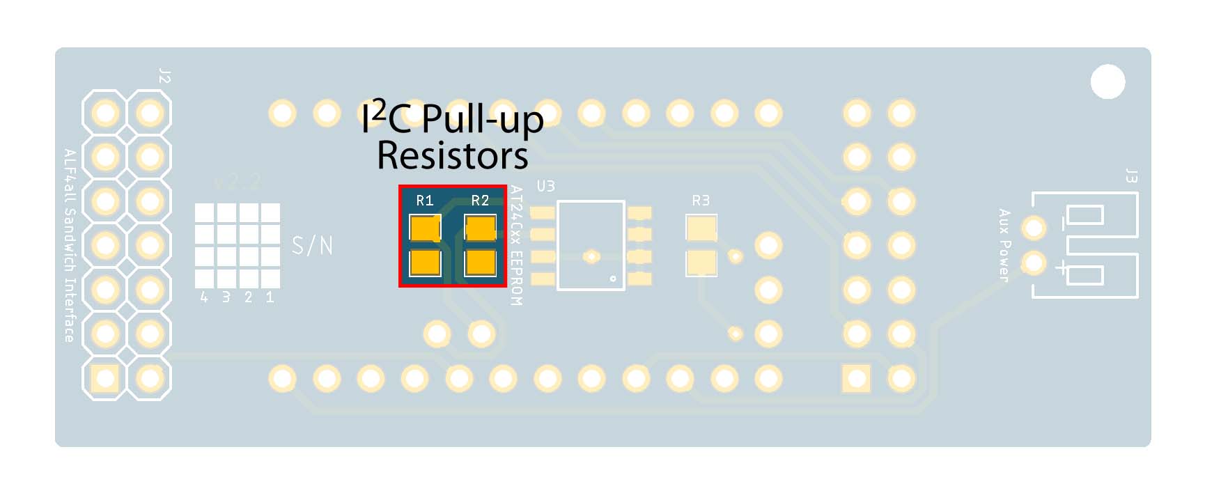 |
I2C Pull-up Resistors
Auxiliary Power Connector
- 2P PH2.0 Right Angle JST Connector
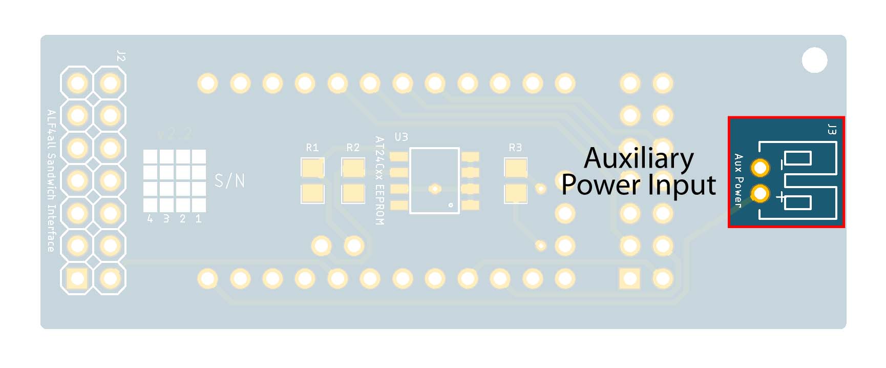 |
Auxiliary Power Connector
The auxiliary power PH2.0 connector, intended for use with a source like a LiPo battery, feeds into the RAW pin on the Pro Mini module, which in turn feeds into the Pro Mini onboard voltage regulator, so we don't need to include a regulator on this input circuit.
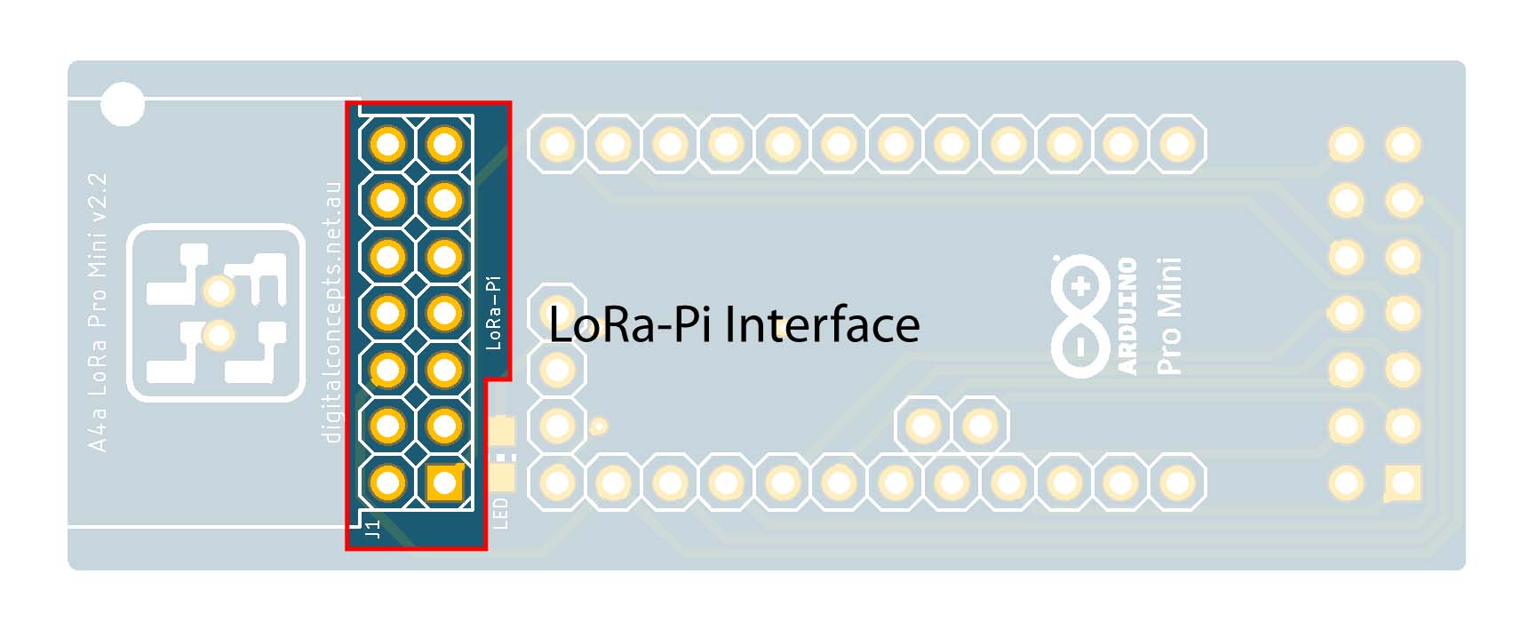
LoRa-Pi Header
- 2×7 Pin Straight Male Header (J1)
 |
LoRa-Pi Header
For my prototyping work, I have used my LoRa-Pi Hat to interface with the RFM95W radio that is used with processors—Espressif or Arduino (Atmel)—that do not include an onboard radio. The simple reason is that this allowed me to create many configuration variations without having to use an individual radio module for every one, rather just swapping the Hat between configurations. The configuration of the RFM95W pins on the LoRa-Pi interface is simply that which allows direct connection to a Raspberry Pi [male] header—the LoRa-Pi Hat, itself, thus has a female header—using the Hallard pin configuration. The LoRa-Pi interface header on the A4a processor boards is thus also a male header, configured as illustrated below.
LoRa-Pi Interface [Processor Board – Male Header] Configuration
Refer to the LoRa-Pi Hat page for the full details of its hardware configuration.


