

Connectors
Board Stack Interconnect Cabling
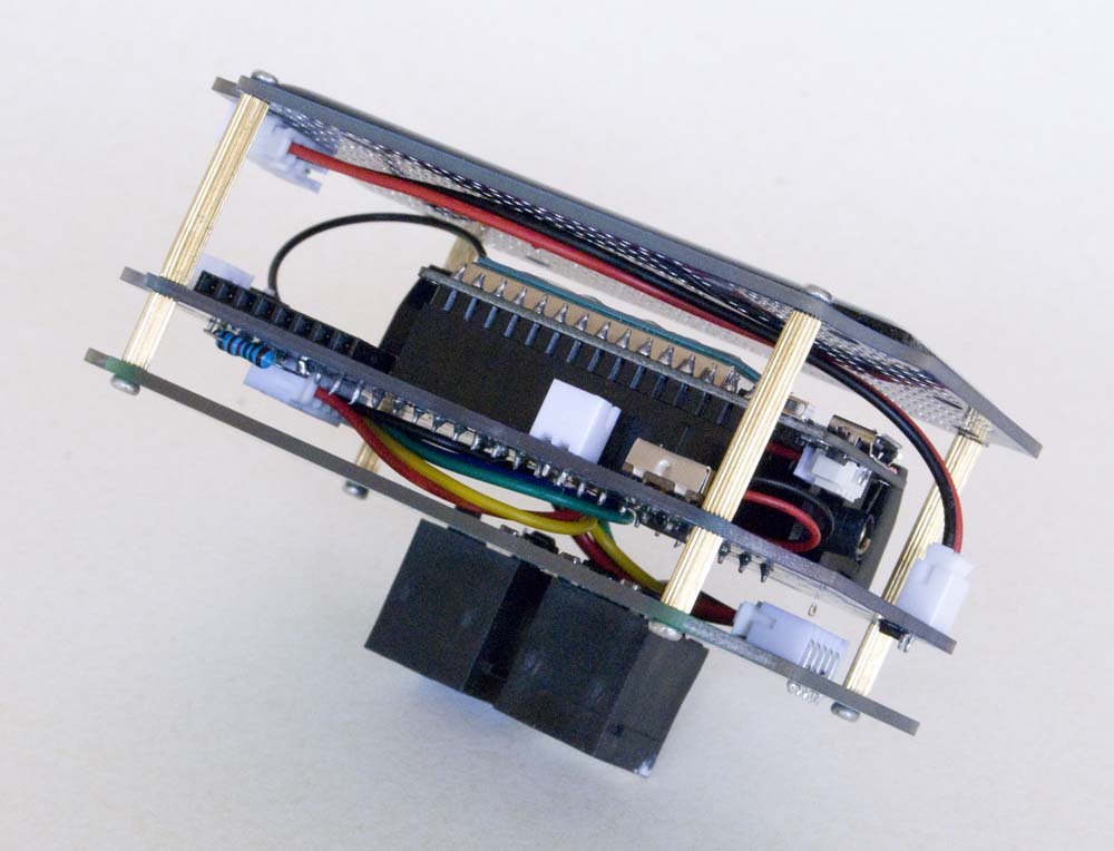
JST connectors are generally configured on individual boards to provide interconnection between boards in a stack. Most commonly, these are 2P–5P PH2.0 connectors, but SH1.0, GH1.25 and RE2.54 (sometimes incorrectly identified as XH2.54) connectors are also used on occasion. The numeric element of the individual connector names indicates the spacing between pins, so the spacing between pins is 1 mm on the SH1.0 connector, 1.25 mm on the GH1.25, 2 mm on the PH2.0 and 2.54 mm, or 100 mil, on the RE2.54 connector.
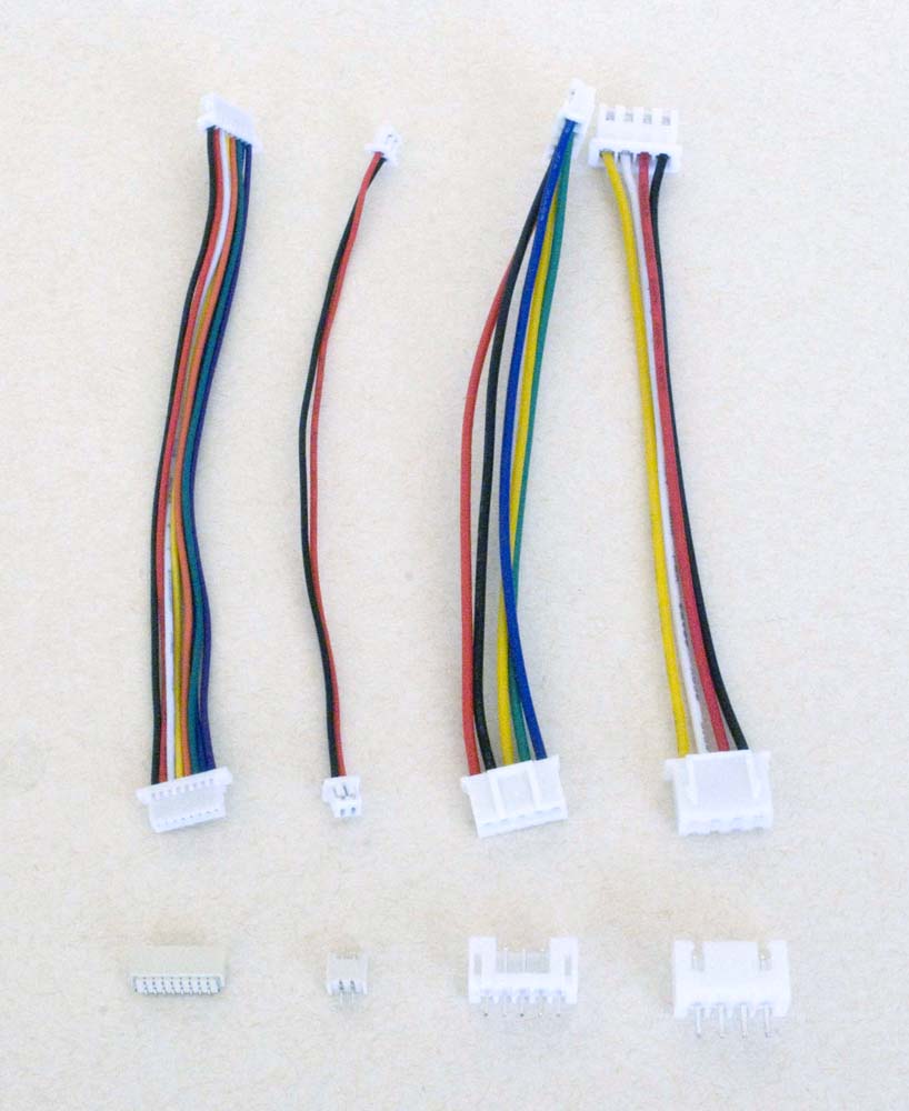
JST Connectors
(L to R: 8P SH1.0 SMD, 2P GH1.25, 5P PH2.0, 4P RE2.54)
The SH1.0 sockets are a small, surface mount option that I've played with a little just to see how practical they might be—they're not easy to hand-solder—but not used seriously in any application.
The GH1.25 connectors are effectively what's used on the Heltec dev-boards for their power input, so these connectors are used where power needs to be provided to one of these boards.
The RE2.54 connectors have the advantage that they use the same pin spacing as a standard 100 mil header. Once again, these connectors are generally used where connectivity with another RE2.54 connector is required but they can be used for a remote connection in place of any standard 100 mil header.
Where there might be confusion as to which connector on a board should be used for what, I've tried to use different connectors to make it clear. Unfortunately, I've not been entirely consistent here, and there are still some situations where I have used PH2.0 connectors for several different functions on the same board—PH2.0 connectors are used for both LiPo battery and solar panel connections, for the current monitor and also when connecting a remote power switch.
Solar Panel and LiPo Battery Connectors
The main issue here is the configuration of the cable leads. Some confusion arises as a result of what appears to be the standard colour sequence used in the manufacture of many multistrand [JST] cables, that being as illustrated below.
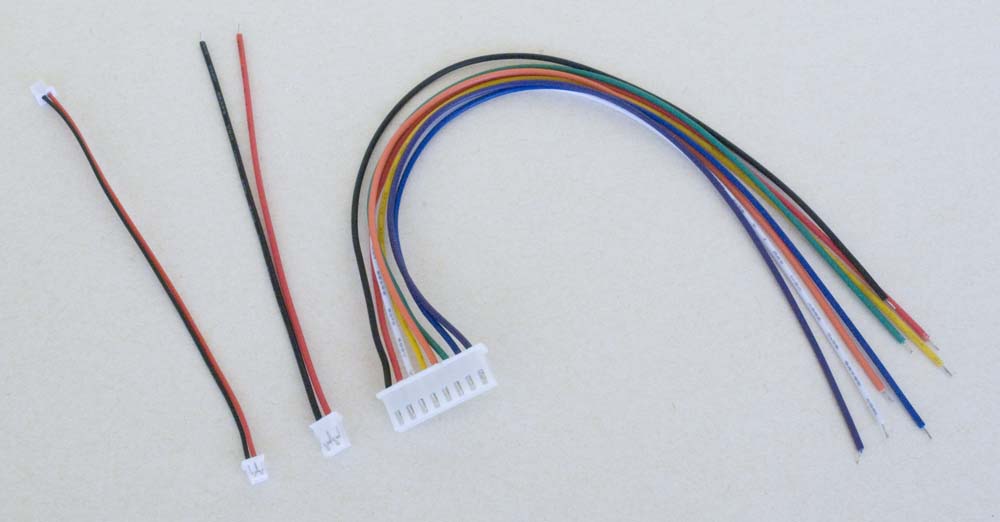
Cable Colour Sequence
The problem is that LiPo batteries, in particular, use the opposite configuration for their leads, which are generally terminated in a JST PH2.0 connector as illustrated below. Solar panels are less of an issue, as they are generally available without attached cables but, when they are, the cable is configured in the same sense as a LiPo battery, which is the opposite to the way 2P pigtails are generally supplied.
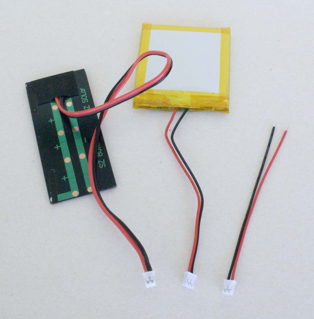
LiPo Battery & Solar Panel Leads vs typical Pigtail configuration
This problem is addressed quite simply by reversing the pigtail leads in the relevant JST connector. To remove a pin from a JST connector, use a sharp knife or similar tool to lift the lug holding the pin in the connector shell (see illustration below) and gently pull on the wire. To replace a wire, simply push it into the connector—the lug will automatically click into place to secure the pin.
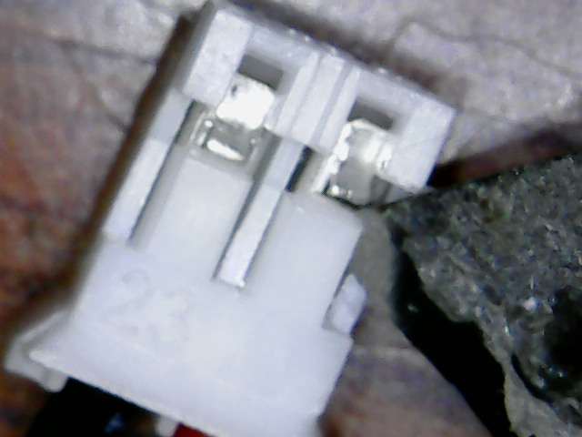
To remove a pin, lift the lug that secures it in the connector housing
Of course, it makes no difference what colour the cables are, as long as positive leads are connected to positive terminals and negative leads are connected to negative terminals. But consistent cable configuration makes it more difficult to make an incorrect connection.
Registered Jack (RJ) Connectors
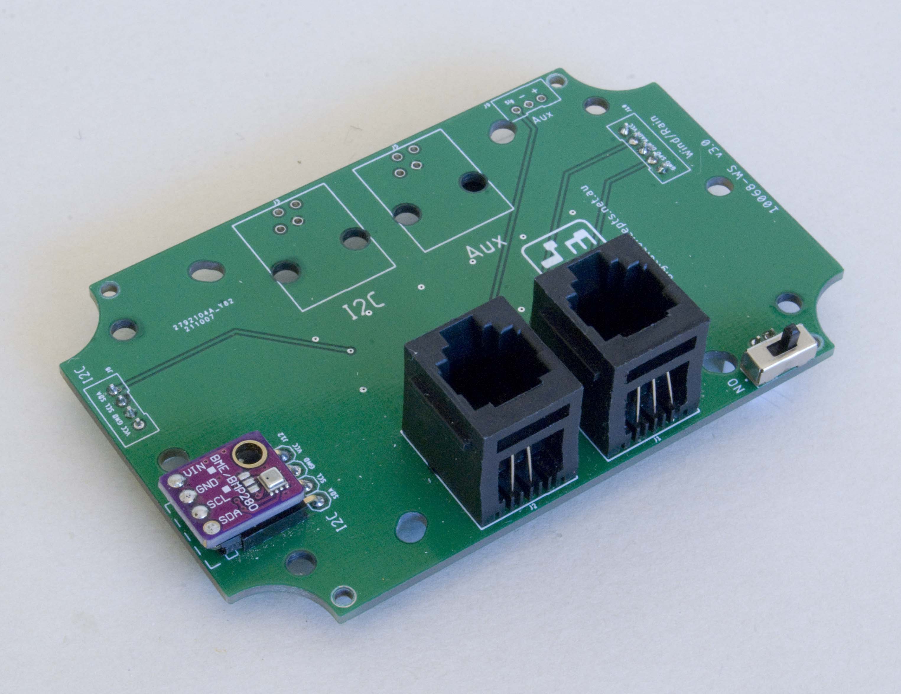
RJ connectors have generally been used where they are the termination provided on a supplied sensor cable, notably the Davis rain collector and anemometer. It is to be noted, however, that these connectors are by no means waterproof, not even vaguely water resistant, and thus generally need to be housed in an enclosure that provides some other measure of protection from ingress of foreign material. It is also to be noted that I have not done this to any great extent in my weather station application and I will report, in due course, on the consequences.
While the RJ part of these connectors is standardised, the PCB connection element does not appear to be—there is quite a range of options that are generally not interchangeable at the PCB level. I have used the items illustrated below, sourced here, in my applications.

RJ Connectors
Waterproof Cable Connectors
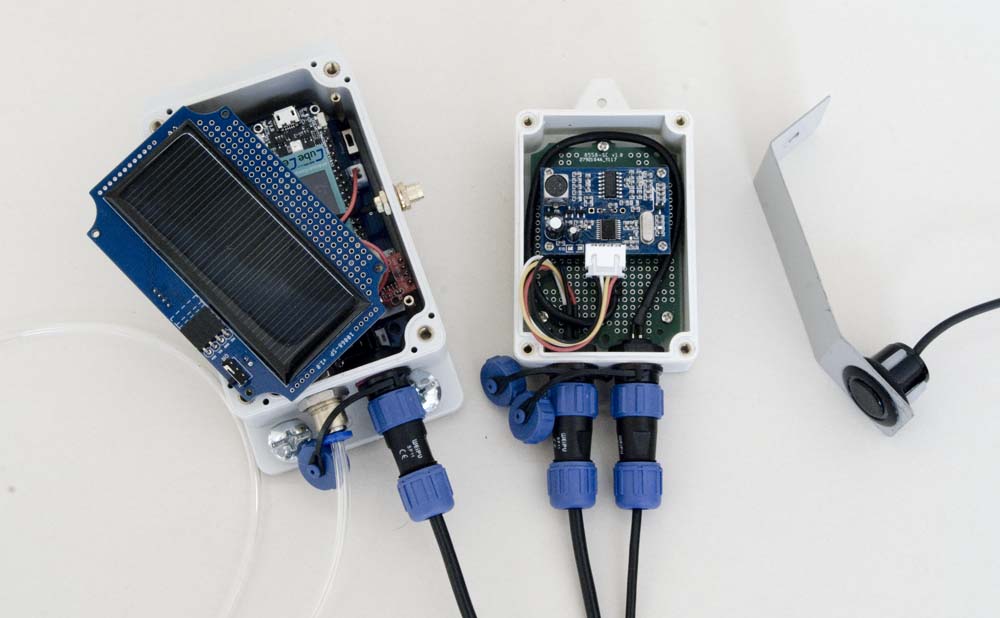
I have generally used WEIPU waterproof cable connectors (refer to the WEIPU website for their complete range of connectors), or cheaper copies thereof, in outdoor applications.

Waterproof Cable Connectors
Note that the smaller WEIPU connectors, which I use where ever possible simply because they take up less room, can generally be specified to accommodate either 3-4mm or 4-6.5mm sized cables for SP11 connectors and 4-6.5mm or 5-8mm sized cables for SP13 connectors. The cheaper connectors only seem to come in one size, generally to accommodate the smaller cable size. I have, however, managed to bore out the cheaper (SP13) connectors to successfully accommodate a larger (8mm) cable.
Panel mount fittings have two flat sides, as illustrated below. SP11: M11 thread—drill hole 9.9mm (practically, that's 10mm) then file the top and bottom flat and file out the rounded sides to 11mm; SP13: M13 thread—drill hole 12.1mm (practically, that's 12mm) then file the top and bottom flat and file out the rounded sides to 13mm.

WEIPU SP11 & SP13 Panel Mount Connector Cut-Outs
While WEIPU offers both male and female plugs and sockets, I have generally standardised on using male plugs—the ones with pins—on cables and female sockets on enclosures as illustrated below.

WEIPU Female Socket and Male Plug
Magnetic USB Charging Cable
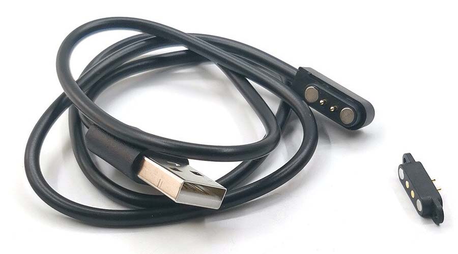
This was a neat alternative, which I found here (although I now believe that these cables are incorrectly configured— see note immediately below), to direct USB connection for the purpose of powering a node and/or charging its battery.
BUYER BEWARE! I just got bitten! The last batch of cables that I ordered, admittedly from a different supplier, have the opposite polarity (which I now believe to be the correct polarity) to that of my original batch. The specs, including the Brand Name (HBXINTAO), were supposedly identical, but the magnets connect in the opposite sense rendering cables from the two batches incompatible. The only difference I can see in the two advertisements is that the first claims to be Samsung-compatible while the second omits any such claim.
One of the magnets on the 'socket' (i.e. not the connector on the end of the cable) is painted red, and this magnet on the second batch is indeed adjacent to the positive pin of the connector, while on the first batch it was adjacent to the negative pin (which I remember thinking was curious).
I have ordered some more cables from the original supplier to see whether, maybe, that first batch was misconfigured or whether there are actually two different configurations in circulation. The latter would be a serious problem because I can see no way of specifying the polarity of the magnets when ordering, as the documentation provided by both suppliers relating to magent polarity is identical.
UPDATE: I have received the second batch from the original supplier and they are also [I believe] incorrectly configured, the same as the original cables. While the very first [incorrectly configured] cables I purchased had moulded 'plugs' and can't readily be modified, the last batch had plug heads that could be 'opened', with a little persuasion. I used a scalpel between the two parts to break the bond on each side (they look like they've been glued with a tiny spot of glue, so this task is fairly easy), removed the 'head', swapped the two magnets over (they just slide out the back of the connector) so that the positive lead on the USB cable connects to the 'red' magnet on the 'socket', then glued the head back together with a couple of spots of super glue.
In preparing this update, I have also found other stores on AliExpress that do explicitly identify the polarity of their connectors and offer both orientations. There would clearly appear to be a requirement for both, although I'm not aware of an application for a reverse polarity cable...
To accommodate the connector, a 4mm slot needs to be cut in the wall of the enclosure—drill two 4mm holes, 10mm apart, then drill/cut/file out the material in between the two holes.
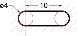
Connector Cut-Out
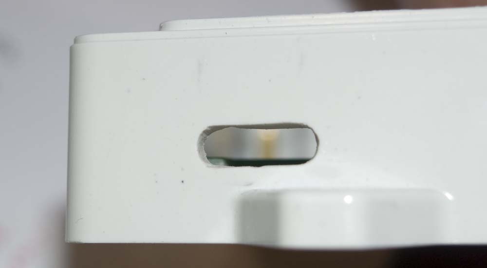
Enclosure Slot
External Power [DC-xxx] Connectors
I haven't actually configured any of these on a board yet, so...
Details pending...
Air Hose Quick Couplings
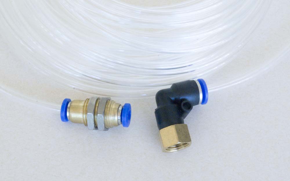
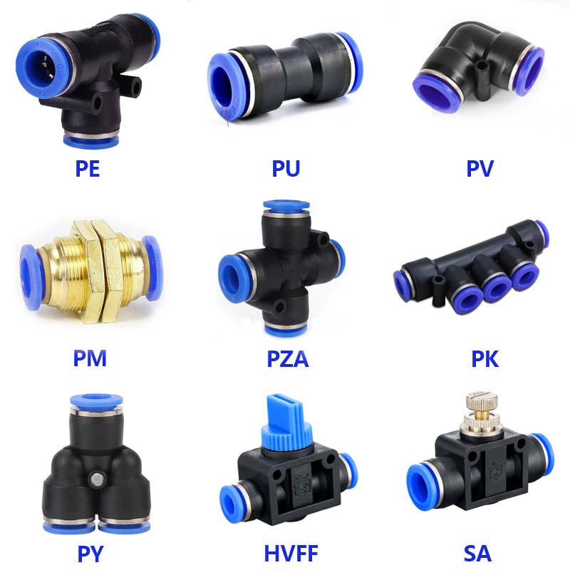
The connectors used for the pressurised air line in the AWTS application can be purchased here. A wide range of fittings is available, including:
 |
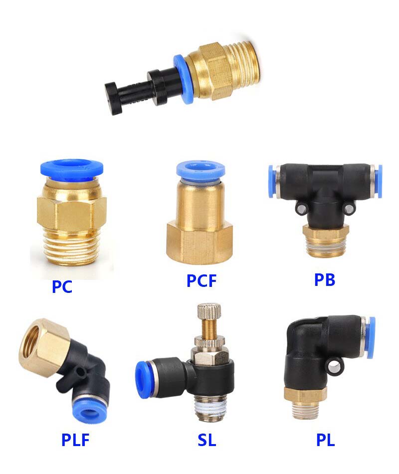 |
Air Hose Couplings
To connect to the sphygmomanometer used in the AWTS application, use 4 (O.D.) × 2.5 (I.D.) mm hosing and 4 mm couplings. The PM-type bulkhead connector (see above) fits in a 12 mm hole.