

TPL5010 Watchdog Timer Module
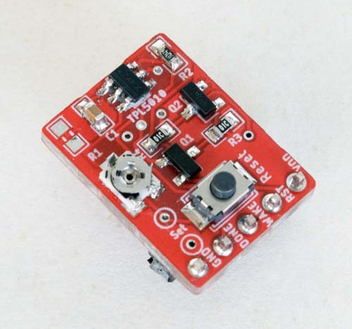
Board Layout
The watchdog timer daughter board circuit is based on the TI TPL5010 timer IC and illustrated in the schematic below.
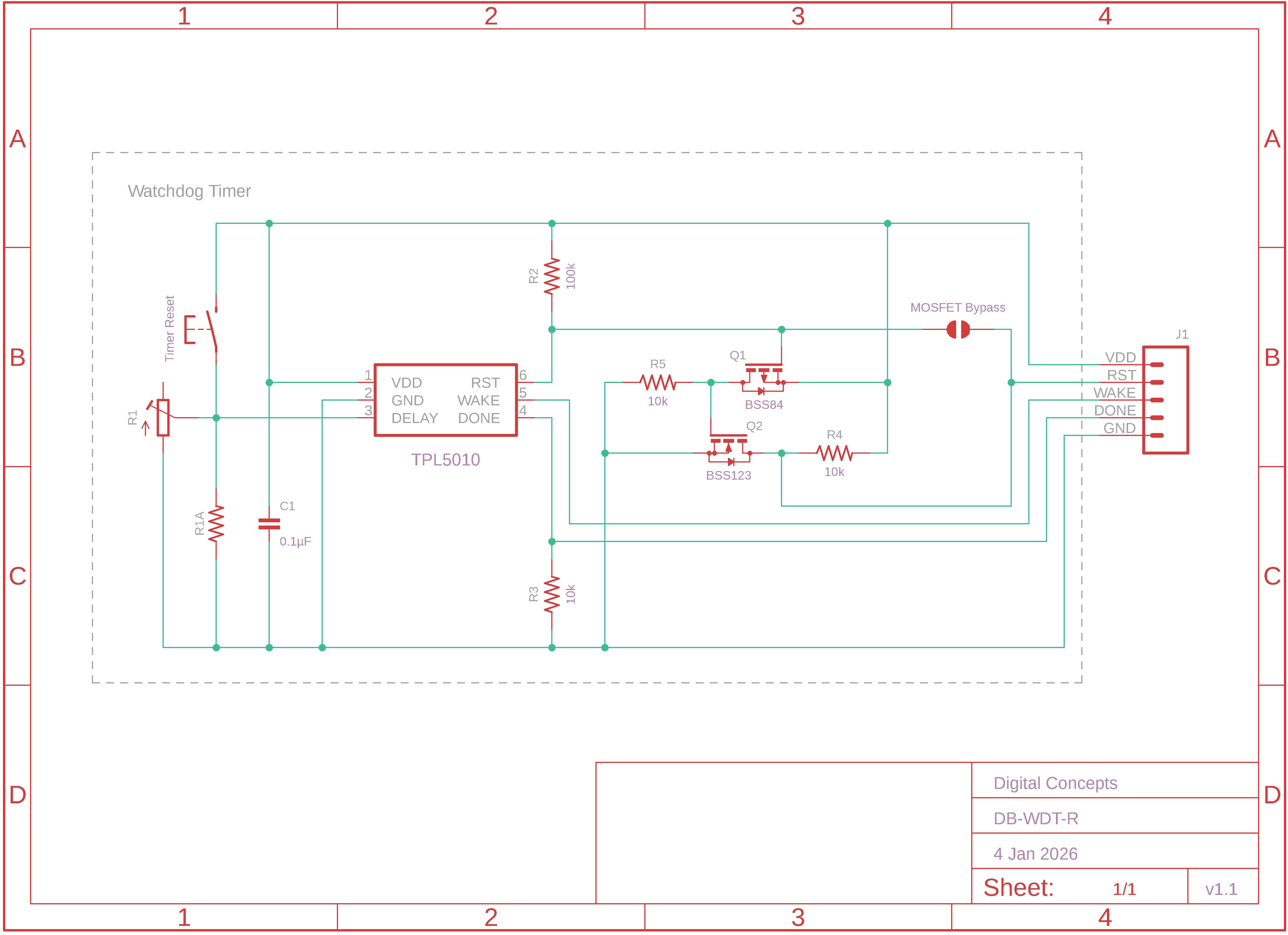
Watchdog Timer Schematic
Note the inclusion of several components in addition to the basic timer circuit:
- The option is provided to use either a fixed value resistor or a trimpot, at least one of which is required but both can be included if deemed appropriate to modify the range available through the trimpot, to set the timer timeout period. The miniature trimpot used in the present configuration does not offer the sensitivity of the larger Bourns trimpots, but it takes up much less real estate and has proven more than adequate for the present application.
- Tap points are provided to facilitate the setting of the timer timeout period resistance in configurations that employ the trimpot option.
- From v1.1, the option is provided to configure a shunt [pull-down] resistor on the
DONEpin if required to generate the timeout periods as identified in the datasheet (see comment below). - The reset button, which provides a mechanism to manually reset the timer, is optional and not required for normal timer operation.
- The MOSFETs switching arrangement was included to address a problem where the TPL5010 was apparently not 'strong' enough to pull the
RSTpin, on some host processor modules, to ground in order to trigger a reset. The MOSFET arrangement has the effect of connecting the host processorRSTpin directly to ground when triggered, rather than relying on the TPL5010 to make the connection internally (more discussion on this issue is provided in the Peripherals > Watchdog Timer page on this website). The MOSFETs are, nonetheless, optional but, if not used, the bypass solder jumper adjacent to the MOSFETs must be bridged.
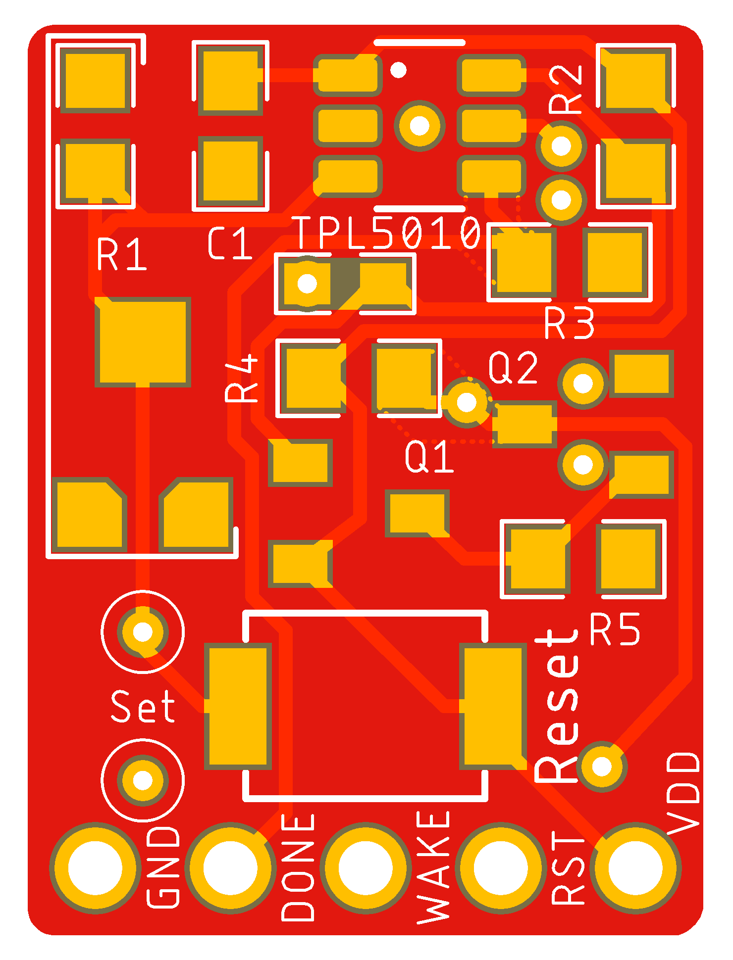
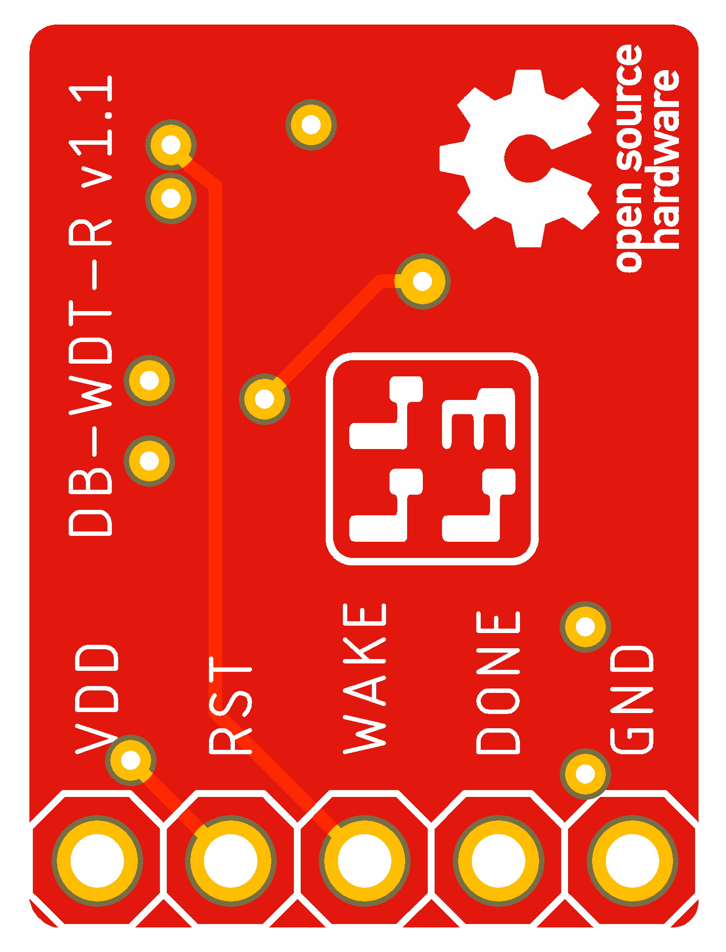
| Top | Bottom |
|---|---|
|
|
Watchdog Timer Daughter Board PCB [v1.1]

|
Watchdog Timer Daughter Board Eagle CAD Files | [33 KB] |
|
|
Watchdog Timer Daughter Board CAM Files | [71 KB] |
Setting the Watchdog Timeout Period
The relationship between the resistance set through [trimpot and/or fixed] resistors R1 and the timer timeout period is described in detail in the TPL5010 datasheet. What doesn't appear in the datasheet is the advice that the DONE pin needs to be pulled to GND at startup, through a shunt resistor (10kΩ recommended) if necessary, for the timing to be set as described.
In the present case, with no shunt resistor and the DONE pin effectively left floating, timings appear to be around double those quoted in the datasheet. The relationship between the resistance and the timer timeout period still appears to be predictable, so this is probably only an issue if it is important that the timings be as defined in the datasheet.
Just for reference, the table below lists times that were measured, both with and without the inclusion of a shunt resistor, together with some of the theoretical resistance values for commonly used times taken from the datasheet.
Resistance vs Time
| Resistance (kΩ) | Measured | Theoretical | |
|---|---|---|---|
| Shunt | Float | ||
| 10 | 00:00:08 | 00:00:16 | |
| 11.20 | 00:00:10 | ||
| 16.78 | 00:00:30 | ||
| 20 | 00:00:47 | 00:01:37 | |
| 20.02 | 00:01:00 | ||
| 29.35 | 00:02:00 | ||
| 30 | 00:02:10 | 00:04:06 | |
| 39.11 | 00:04:00 | ||
| 40 | 00:04:17 | 00:08:36 | |
| 49.38 | 00:07:00 | ||
| 50 | 00:07:22 | 00:14:39 | |
| 57.44 | 00:10:00 | ||
| 60 | 00:11:17 | 00:22:27 | |
| 70 | 00:16:04 | 00:32:00 | |
| 77.57 | 00:20:00 | ||
| 80 | 00:21:47 | 00:43:49 | |
| 90 | 00:29:11 | 00:57:19 | |
| 92.43 | 00:30:00 | ||
| 100 | 00:37:48 | 01:14:35 | |
| 124.91 | 01:00:00 | ||
For my applications, which don't require a timeout period of more than 30 minutes, I configure a 100kΩ trimpot at R1. For longer timeout periods, up to the stated 2 hour limit of the TPL5010 IC, a trimpot with a higher resistance range or, if all that is required is a fixed timeout period, a resistor of appropriate size, would need to be configured.