

Battery Management Module
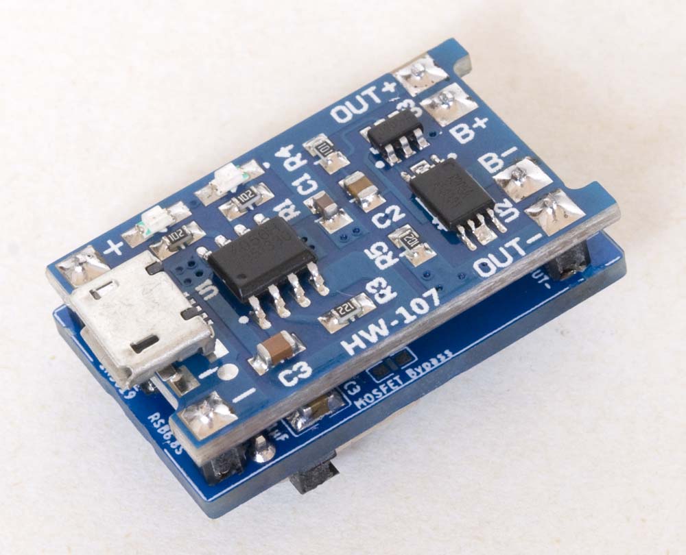
Board Layout
The present battery management daughter board circuitry includes a TP4056 battery charge module, the battery voltage measurement circuit described elsewhere on this website and switching circuitry, also described elsewhere on this website, to manage power usage when connected to an external source. The full circuitry is illustrated in the schematic below.
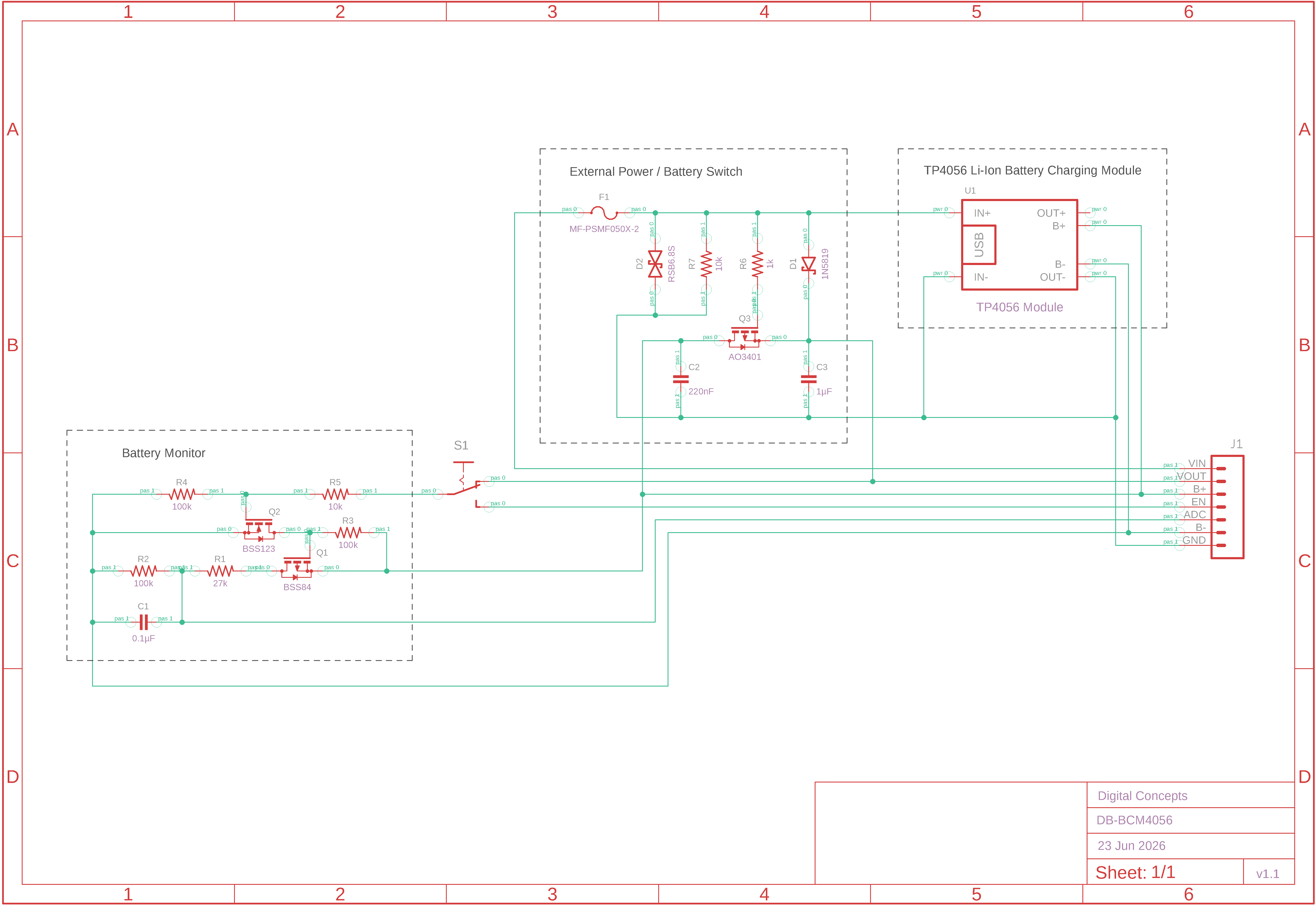
Battery Charge Manager Schematic
This circuitry was moved off the original BCS-A4a boards, to a daughter board, to facilitate the reuse of components during prototyping. The use of daughter boards for specific, common functions also simplifies the subsequent design of host PCBs (cf.10068-BCS-A4a vs 10068-BMS-A4a).
| Top | Bottom |
|---|---|

|

|
Battery Charge Manager Daughter Board PCB [v1.1]

|
Battery Charge Manager Eagle CAD Files | [27 KB] |
|
|
Battery Charge Manager CAM Files | [83 KB] |