10068-BHWL[3] PCB
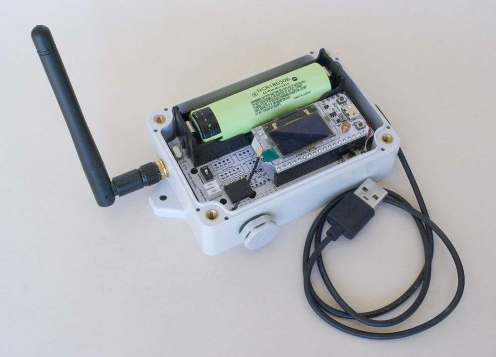
The BHWL (Battery-Heltec-WiFi LoRa) 'base' board is specifically designed to support the Heltec WiFi LoRa 32 V2 development board, while the BHWL3 board is designed to support the V3 board. The two boards are based on different MCUs (ESP32-S2 vs ESP32-S3 processor and SX1276/SX1278 vs SX1262 LoRa Node chip) and, while both boards provide essentially the same functionality, the pinouts of each reflect those of the intended host MCU and are entirely different.
The functionality of the BHWL3 board is actually a development of that of the BHWL board and incorporates an external watchdog timer that is not present on the BHWL board—given that the Heltec WiFi LoRa 32 V2 board is no longer in production, I am not planning any further development of the BHWL board.
Board Layout
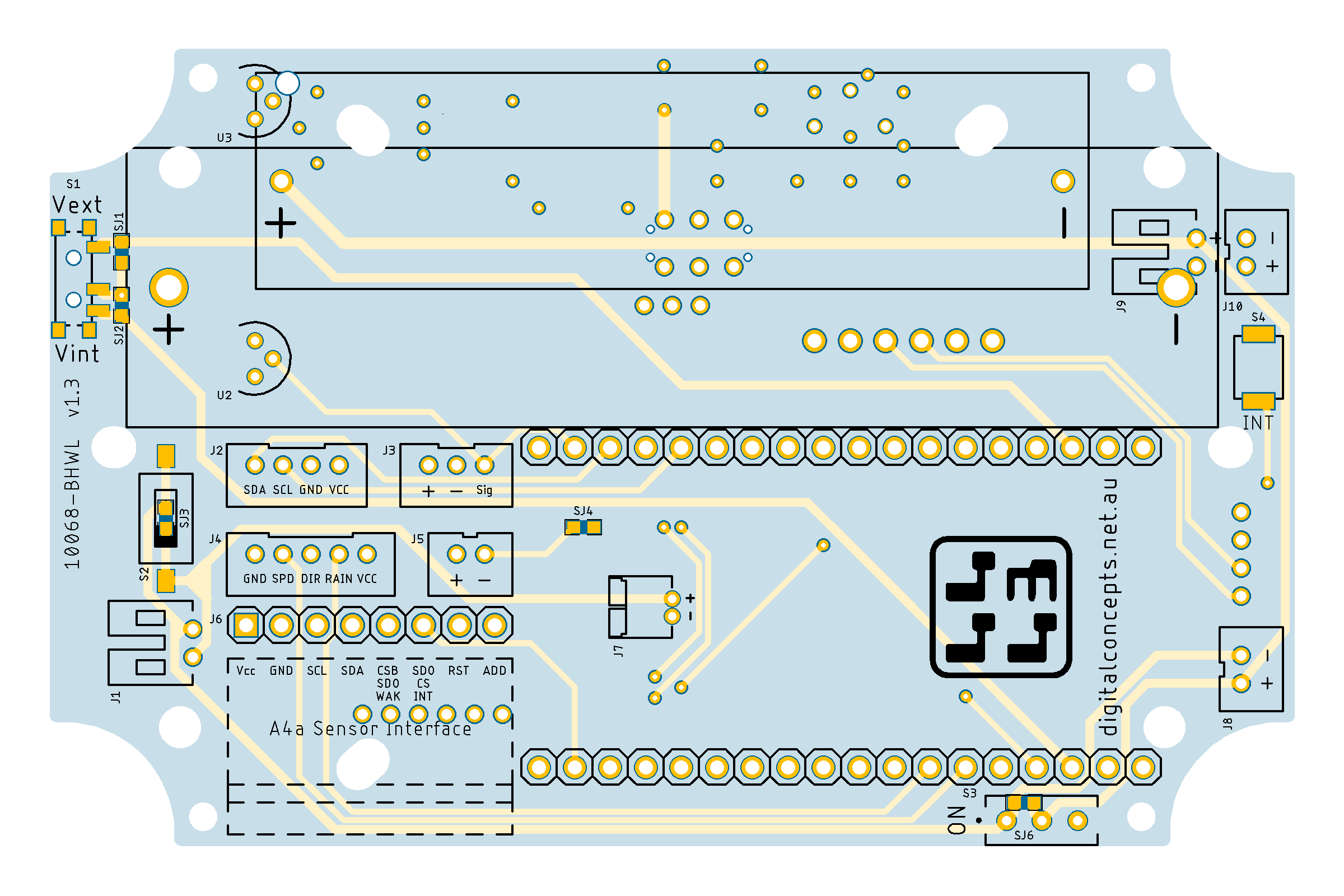
The various subsystems of BHWL board are identified in the BHWL (V2) board schematic and laid out as illustrated below:
| Top | Bottom |
|---|---|
 |
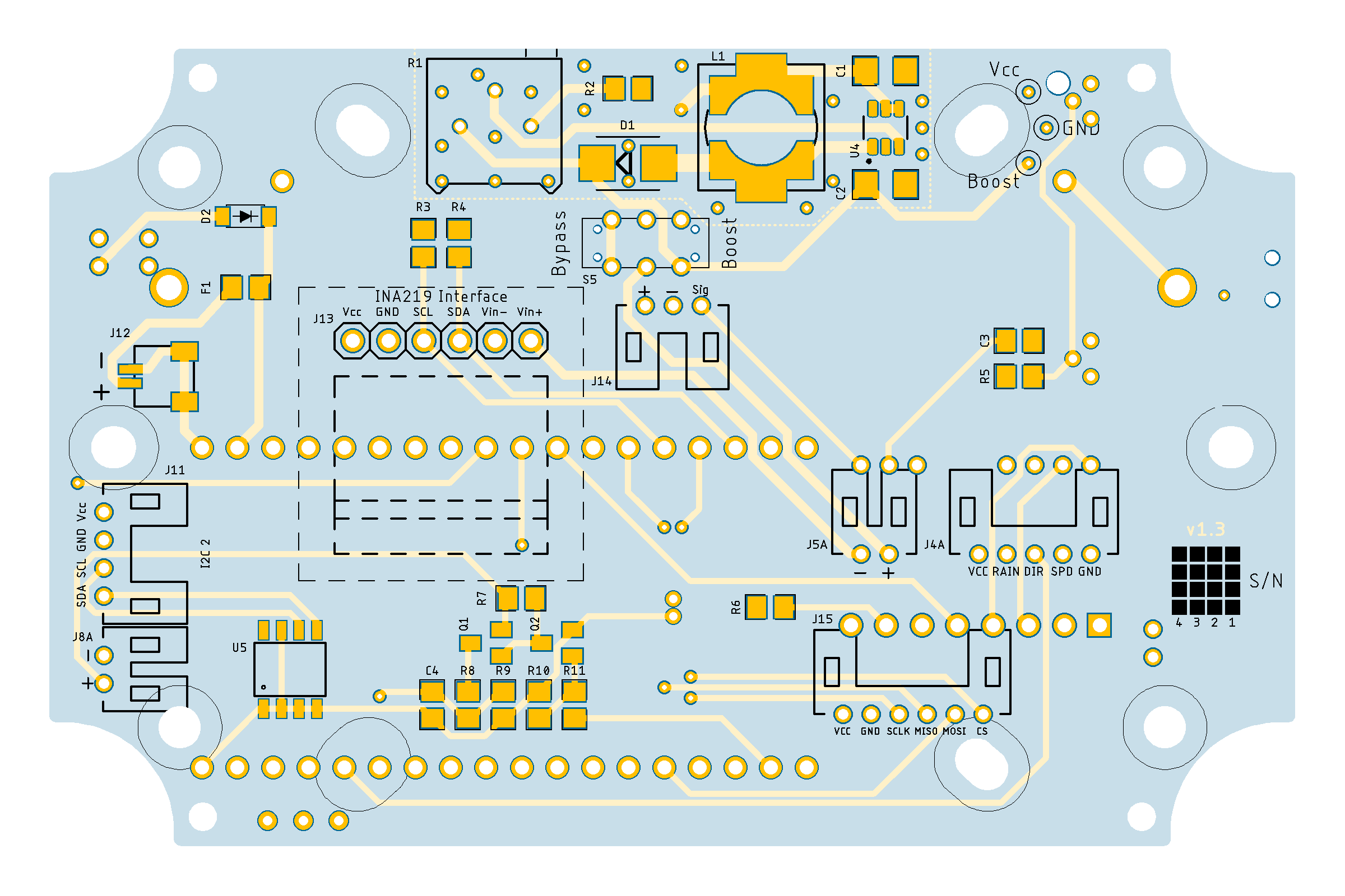 |
10068-BHWL [v1.3] PCB
See here for CAD and CAM files.
While I have endeavoured to accommodate the more minor differences between the Heltec WiFi LoRa 32 V1 and V2 MCUs in the BHWL board, there is, for example, no Vext pin on the V1 MCU so some features will not be available if using that module.
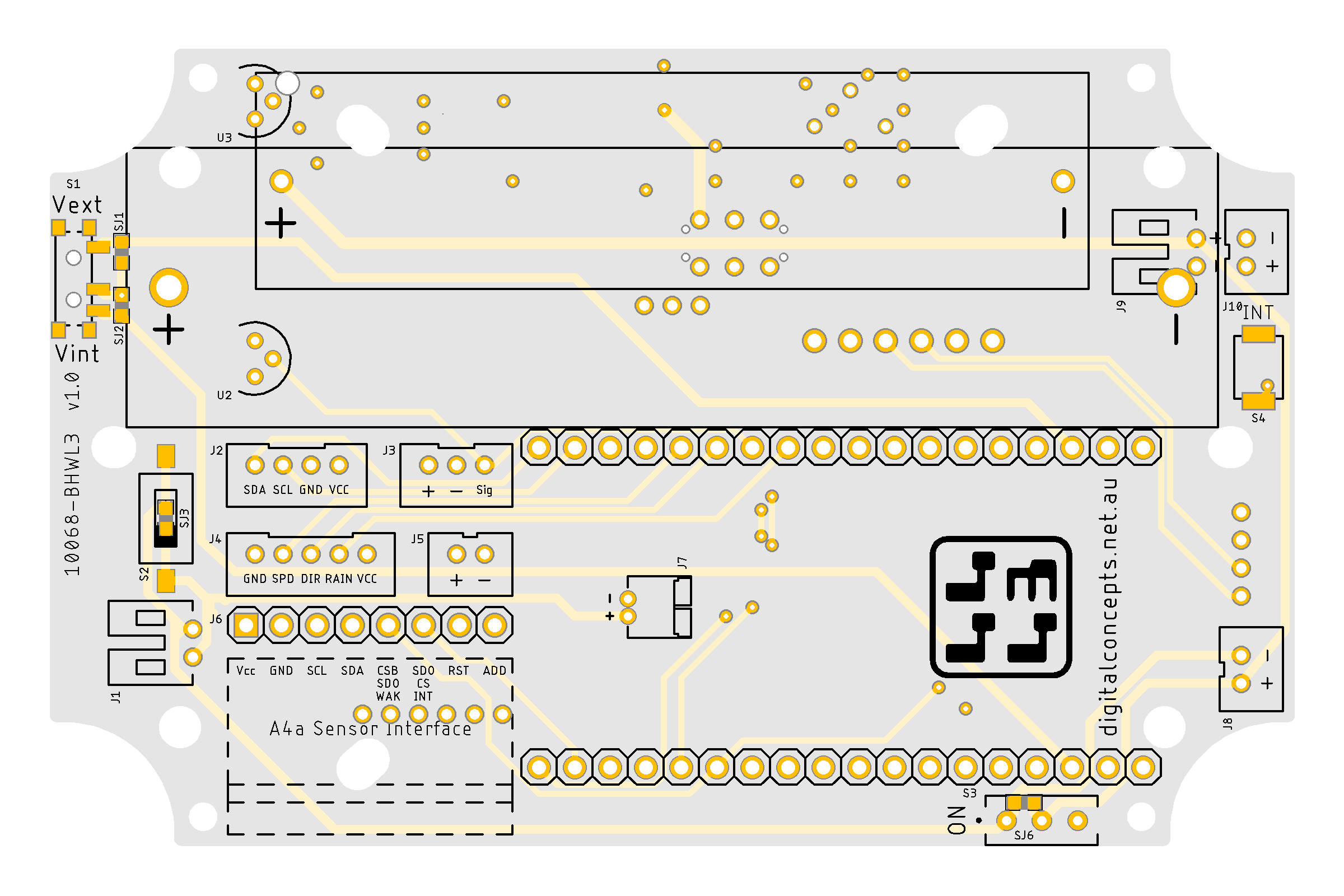
The various subsystems of BHWL3 board are identified in the BHWL3 (V3) board schematic and laid out as illustrated below:
| Top | Bottom |
|---|---|
 |
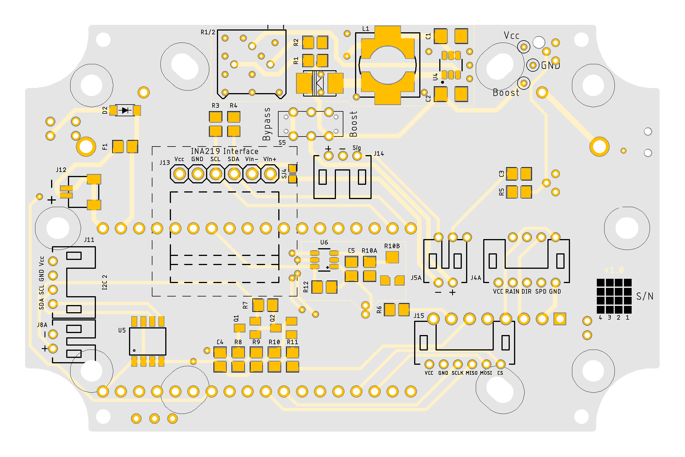 |
10068-BHWL3 [v1.0] PCB
See here for CAD and CAM files.
Configuration
The BHWL (Battery-Heltec-WiFi-LoRa) and BHWL3 (Battery-Heltec-WiFi-LoRa V3) boards are intended to supplement the on-board features of the Heltec WiFi LoRa 32 V2.1 and V3 development boards respectively.
The BHWL3 board is yet to be fully tested.
Battery Power Management
See here for Heltec recommended sketch details.
External [Magnetic USB] Power Connection
While this board can be battery powered, because it effectively never sleeps this is really only a UPS solution. In the present case it is intended that the board be powered through an external power source via the magnetic USB cable described elsewhere on this site. Power is thus provided through the 5V pin on the Heltec WiFi LoRa 32 module as indicated in the board schematic (V2 illustrated, but the same applies to the V3 board).
Further details pending

