9575-BPHC PCB

Board Layout
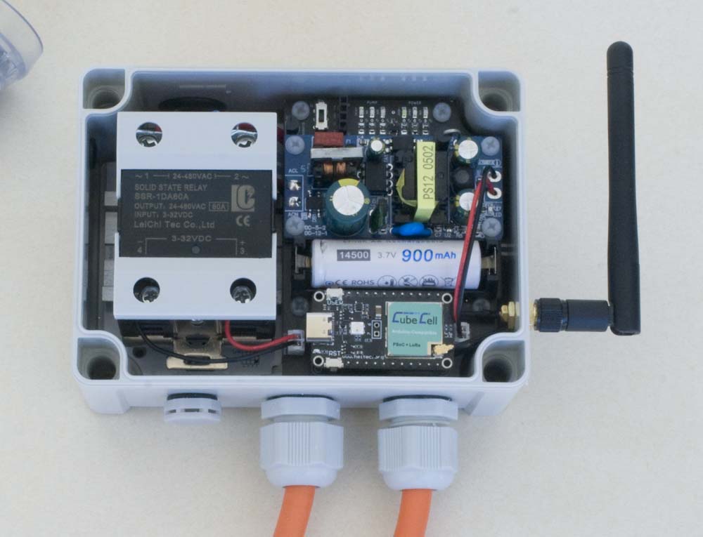
This board is designed to be used in a 'sandwich' configuration with the 13095-BP-R PCB in the Power Switch Node.
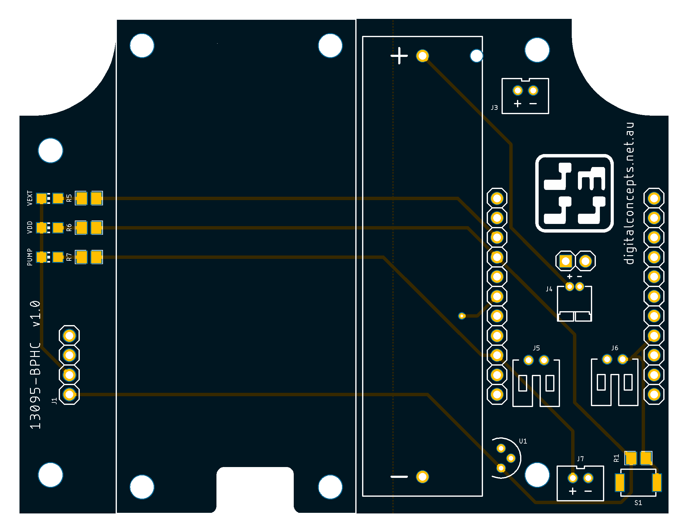
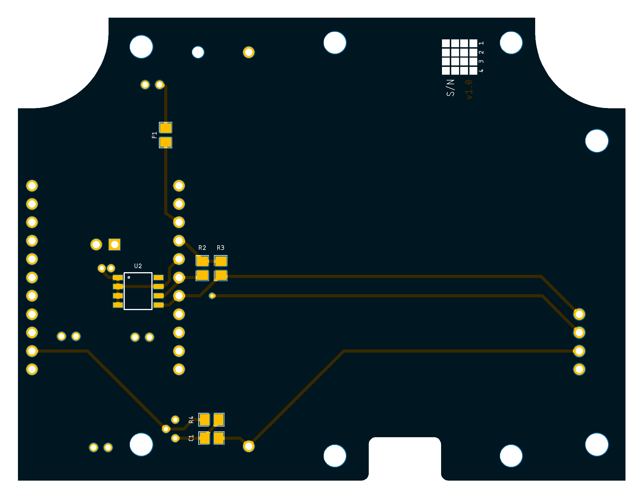
The various subsystems are identified in the board schematic and laid out as illustrated below:
| Top | Bottom |
|---|---|
 |
 |
9575-BPHC [v2.2] PCB
See here for CAD and CAM files.
Configuration
Details pending

