

MT3608 Boost Converter Module
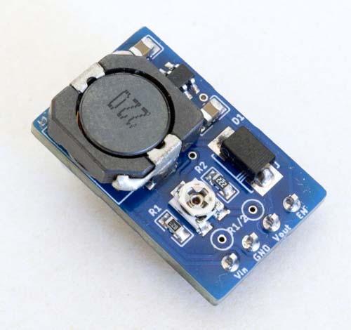
Board Layout
This is an implementation of a boost converter based on the (Olimex) Aerosemi MT3608 IC, using a slightly enlarged version of the form factor used in the FP6277 and SX1308 modules described on this site to accommodate a larger inductor and a trimpot to support a range of output voltages. Like the SX1308, the MT3608 takes an input in the range 2~24V and can generate an output of up to 28V.
The schematic diagram for this module is effectively taken from that of the commonly available commercial MT3608 module, but uses a smaller, SMD trimpot. The physically smaller trimpot is not as finely adjustable as the larger Bourns-style one used in the commercially available version but it helps to achieve the goal of keeping the overall footprint of the module as small as possible.
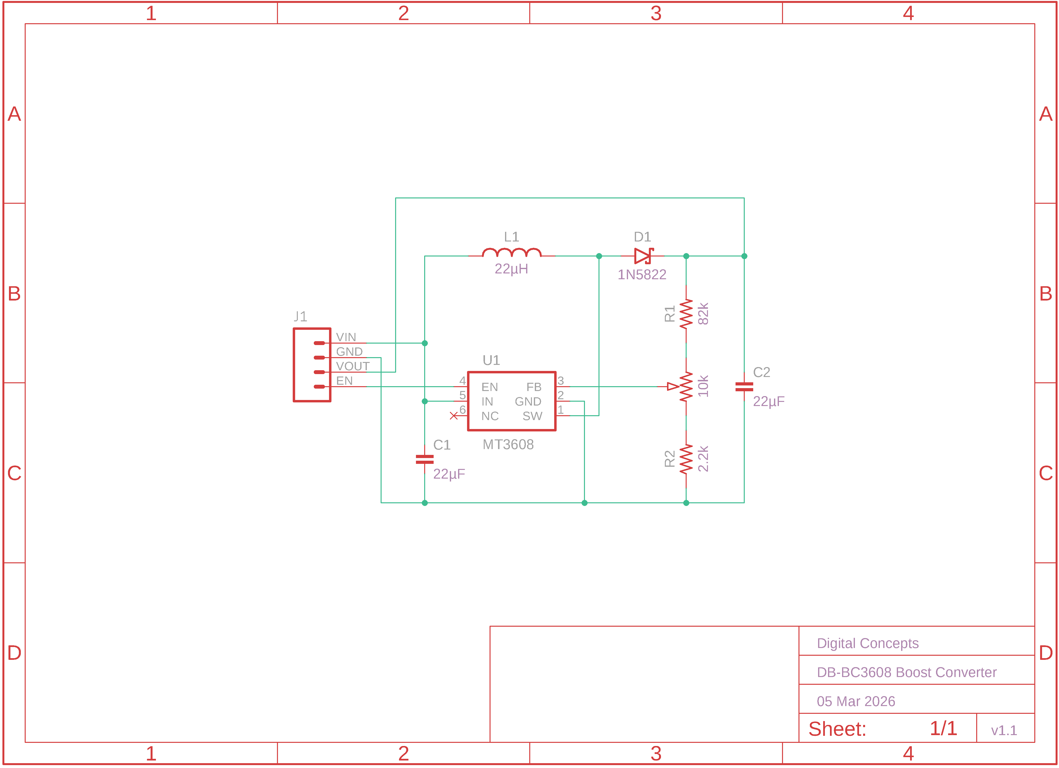
MT3608 Boost Converter Module Schematic
The values of the resistors used will ultimately determine the output voltage that can be configured. Using the values indicated in the schematic, R1 = 82kΩ, R2 = 2.2kΩ with a 10kΩ trimpot, theoretically allows the configuration of output voltages across the range 4.6V ~ 25.7V. I've only made up one board to date, and it had a measured range of 4.85 ~ 25.9V.
| Top | Bottom |
|---|---|
|
|
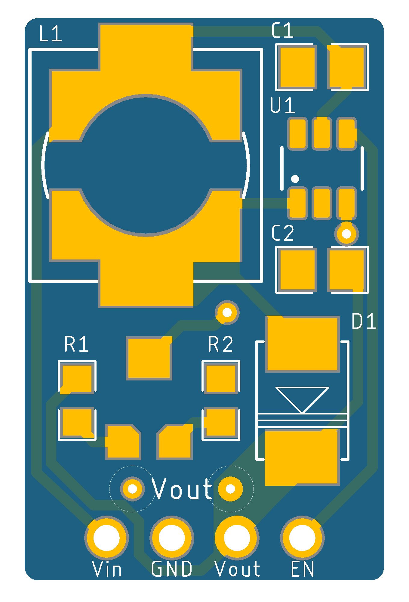
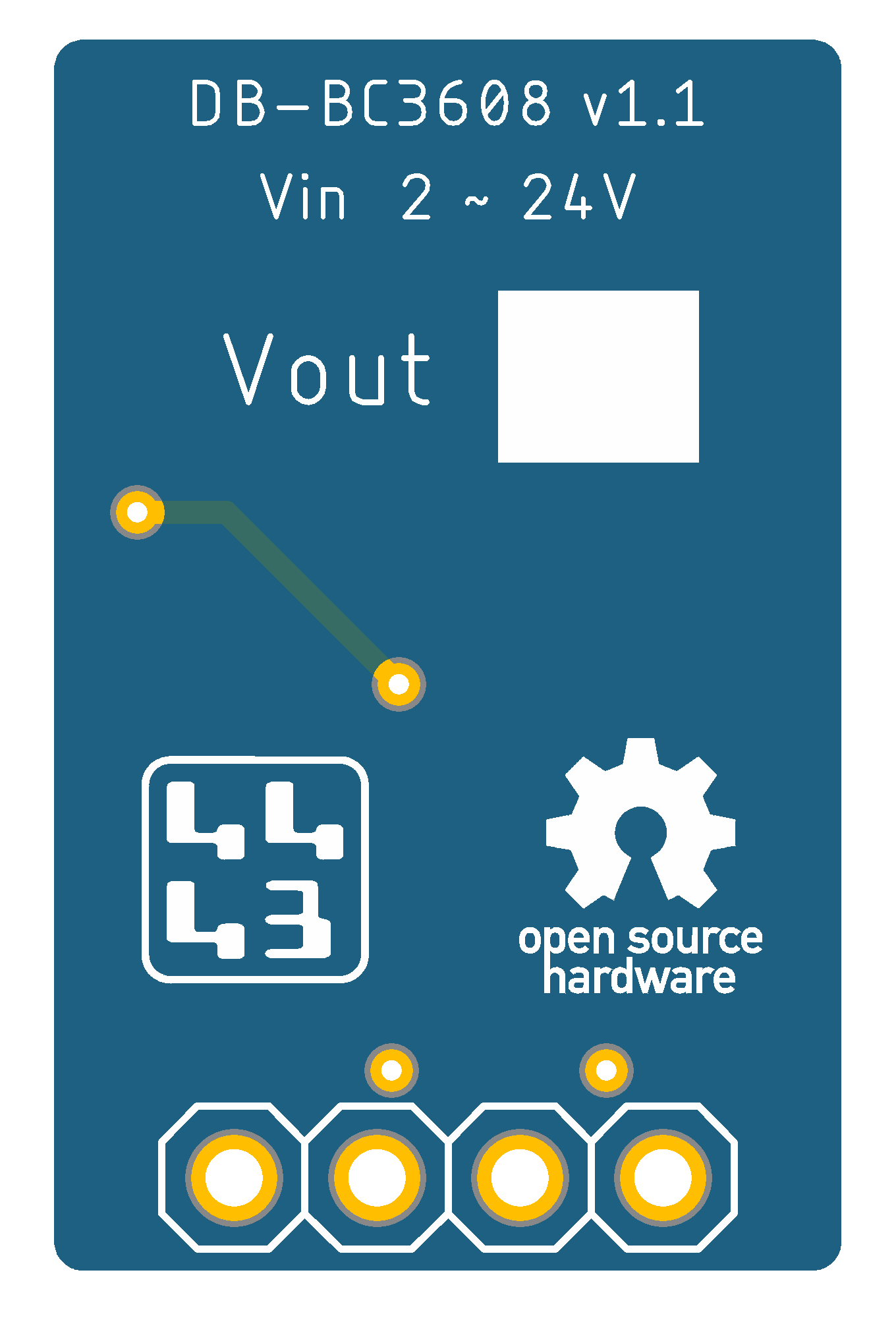
MT3608 Boost Converter Module PCB

|
MT3608 Boost Converter Module Eagle CAD Files | [32 KB] |
|
|
MT3608 Boost Converter Module CAM Files | [60 KB] |
The unusual shape of the inductor landing pad is designed to support a range of inductor styles and sizes.
As a footnote here, the [Aerosemi] MT3608 and [Sunrom] ST1308 share the same SOT23-6 packaging and would appear to be fully interchangeable ICs. With the exception of the branding, the datasheets for the two (MT3608 and SX1308) are identical, right down to the illustrations and performance graphs.