

SX1308 [24V] Boost Converter Module
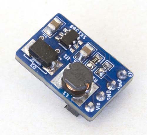
Board Layout
This is an implementation of a boost converter based on the Sunrom SX1308 IC, using the same form factor as the FP6277 module. The SX1308 takes an input in the range 2~24V and can generate an output of up to 28V, depending on the voltage divider resistors that are configured.
Resistor Configuration Examples
| Resistance (Ω) | Vout (V) | |
|---|---|---|
| R1 | R2 | |
| 110k | 15k | 5 |
| 140k | 10k | 9 |
| 130k | 910R | 9.2 |
| 190k | 10k | 12 |
| 130k | 680R | 12.1 |
| 390k | 10k | 24 |
The 5V and 24V values can be achieved with standard resistors, but the closest we can get to 9V and 12V with commonly available resistor values would seem to be 9.2V and 12.1V respectively, as illustrated in the table above.
The schematic diagram below illustrates the [resistor] configuration for a 24V boost converter.
![SX1308 [24V] Boost Converter Module Schematic](content/support/variants/daughter/boost/SX1308 Boost Converter Schematic.png)
SX1308 [24V] Boost Converter Module Schematic
| Top | Bottom |
|---|---|
|
|
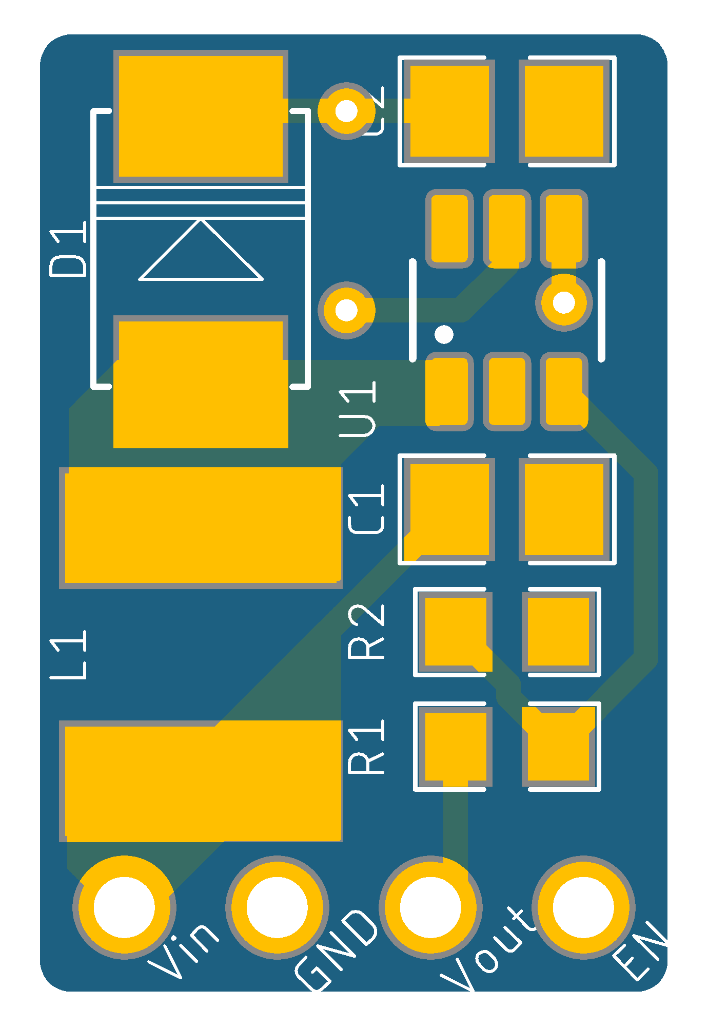
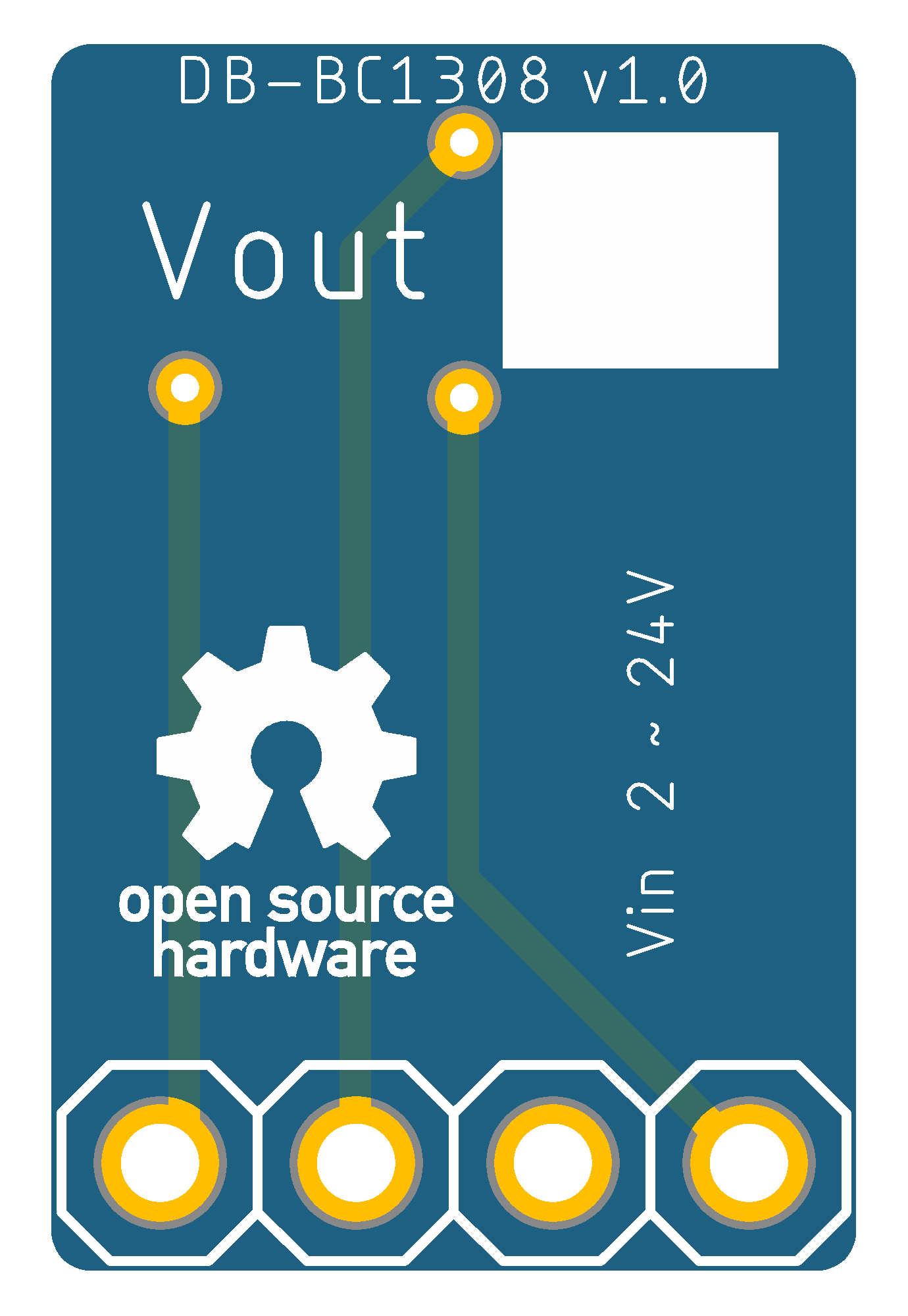
SX1308 Boost Converter Module PCB

|
SX1308 Boost Converter Module Eagle CAD Files | [25 KB] |
|
|
SX1308 Boost Converter Module CAM Files | [60 KB] |
As a footnote here, the [Aerosemi] MT3608 and [Sunrom] ST1308 share the same SOT23-6 packaging and would appear to be fully interchangeable ICs. With the exception of the branding, the datasheets for the two (MT3608 and SX1308) are identical, right down to the illustrations and performance graphs.