

MAX44009 Ambient Light Sensor
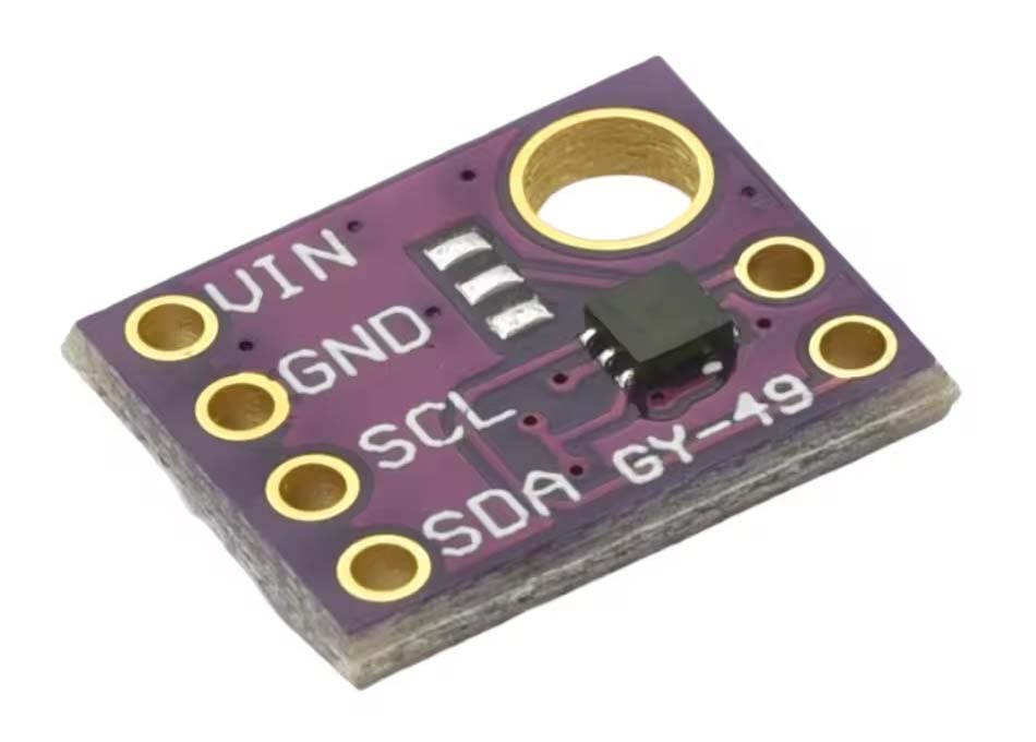
This section deals with the configuration of the MAX44009 ambient light sensor.
Application
TBA
Configuration
Hardware
The MAX44009 sensor module is configured on an I2C bus with a 3.3V supply voltage.
The other two, unmarked pins on the sensor module set the [upper pin] I2C address—tie to GND to set the address to 0x4A or 3V3 to set it to 0x4B—and the [lower pin] interrupt status—if using interrupts, connect to an appropriate processor pin and a pull-up resistor. The configurations illustrated below set the sensor module I2C address to 0x4A and enable the detection of interrupts generated by the sensor module.
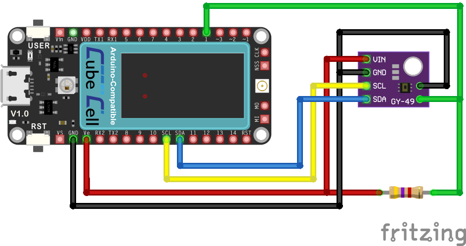
CubeCell Plus - MAX44009 Electrical Circuit
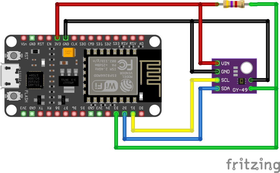
NodeMCU - MAX44009 Electrical Circuit
Pin Configurations
| CubeCell Plus | NodeMCU | MAX44009 |
|---|---|---|
| Vext | 3V3 | VIN |
| GND | GND | GND |
| SCL | D1 | SCL |
| SDA | D2 | SDA |
| GND | GND | ADDR [0x4A] |
| GPIO1 (Pull-Up) | D3 (Pull-Up) | INT |
The I2C address can also be set by bridging the solder jumpers on the module—bridge the upper two pads to set I2C address 0x4A, as shown in the image below, or the lower two to set I2C address 0x4B.
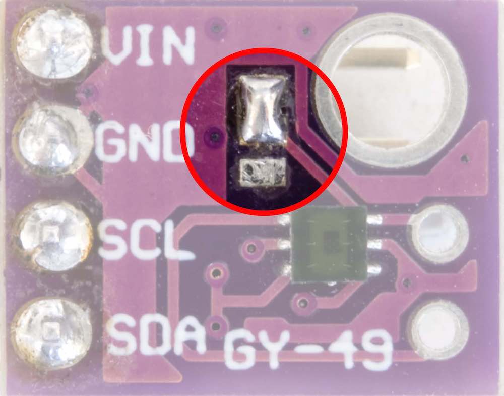
I2C Address Jumpers
Software
Since communication with the sensor is via an I2C bus, that part of the required software is identical for the two platforms. The difference between the two, with the hardware configurations as illustrated, is that the CubeCell Plus configuration supplies power to the sensor via Vext, which must therefore be explicitly turned on before the sensor is used.
See Rob Tillaart MAX44009 library and, one way or another, we will ultimately want to include code to detect/process interrupts, just for the exercise in demonstrating/understanding how they work, if nothing else..
|
Further details pending