

PH-4502C pH Sensor
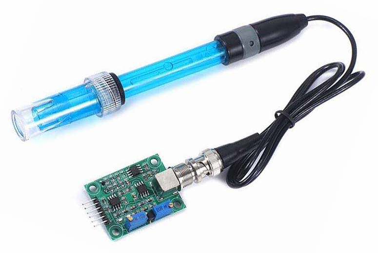
This section deals with the configuration of the PH-4502C pH sensor.
Application
The intention is to use the PH-4502C sensor to measure pH of the water output from an aerated wastewater treatment system (AWTS). It's not clear at the moment, however, whether or not having the sensor permanently located in this environment, taking periodic measurements, will be practical.
Details pending
Configuration
Source material:
Nathaane Isip PH-4502C sensor library
Respberry Pi Example with lots of more general information about usage of the sensor
Details pending
Hardware
The PH-4502C is a 5V sensor that generates output on its Po pin in the range 0~5V, corresponding to pH in the range 0~14 when correctly calibrated. I am yet to confirm it, but I am assuming that the reading taken from the To pin, output from the onboard NTC [Negative Temperature Coefficient] 103 thermistor, will also be in the range 0~5V. The subsequent calculation of the relevant temperature is the subject of discussion on several forums but does not appear to be trivial, as the change in resistance, which is what is actually being measured, is non-linear and requires a bit of maths to derive a corresponding temperature.
Both the CubeCell and ESP32 platforms require the use of voltage dividers to bring these output voltages back to 0~2.4V and 0~3.3V ranges respectively. For the CubeCell platform, a 240kΩ/220kΩ combination will bring 5V back to 2.4V and, for the ESP32, a 130kΩ/220kΩ combination will bring the maximum output voltage back to 3.1V, avoiding the use of the notoriously non-linear top end of the ESP32 ADCs.
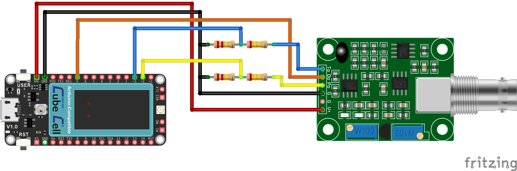
CubeCell Plus / PH-4502C Electrical Circuit
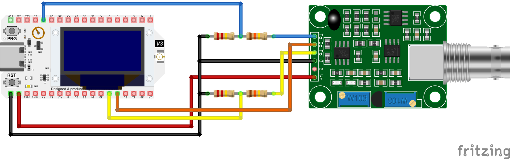
WiFi LoRa 32 (V3) / PH-4502C Electrical Circuit
Pin Configurations
| CubeCell Plus | WiFi LoRa 32 (V3) | PH-4502C |
|---|---|---|
| Vin | 5V | V+ |
| GND | GND | G |
| GND | GND | G |
| ADC2 | GPIO48 | Po |
| GPIO5 | GPIO47 | Do |
| ADC3 | GPIO46 | To |
The controller board contains two trim pots, one used to calibrate the Po output against the pH being measured and the other to set the threshold that triggers signalling on the Do pin.
Further details pending...
Software
Details pending, but in the interim...
The following is a simple code example from CirkitDesigner.
|