Water Level [Pressure] Probe
![HDL300 Water Level [Pressure] Sensor](../arduino/content/images/iot/assembly/sensors/HDL300.jpg)
Application
The HDL300 pressure probe, actually the 2-wire 4~20mA current loop version of a TL-MPM-70G, which is functionally identical, is one of the sensors currently used to monitor the water level in storage tanks on my rural property.
There are, in fact, several similar probes that I have encountered—HDL300, QDY30A, TL-136, TL-MPM-70G and YB2JF to name a few—that all operate in the same fashion and appear to be entirely interchangeable, the operating voltage (5V or 24~36V), hardware interface (2-wire, 3-wire or 4-wire) and [depth] rating (0~20m) of the individual probe notwithstanding.
Configuration
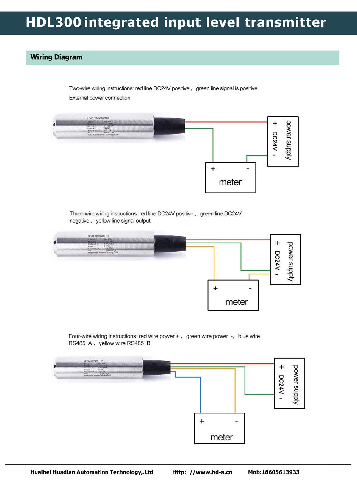
This style of water pressure sensor is generally available in three configurations—2-wire, 3-wire and 4-wire. All configurations include variants that operate over a 12~32V range, with 24V as the typically recommended supply voltage. The 2-wire configuration yields pressure measurements through a 4~20mA current loop, the 3-wire configuration on separate signal wire as a voltage, typically in the 0~5V range, and the 4‑wire configuration reports measurements via an RS485 interface (see RS485 Interface > Water Level). There are also 5V [supply] versions of the 3-wire configuration with signal voltages in the 0~3.3V and 0.5~4.5V ranges.
Hardware
2-Wire [24V, 4~20mA] Configuration
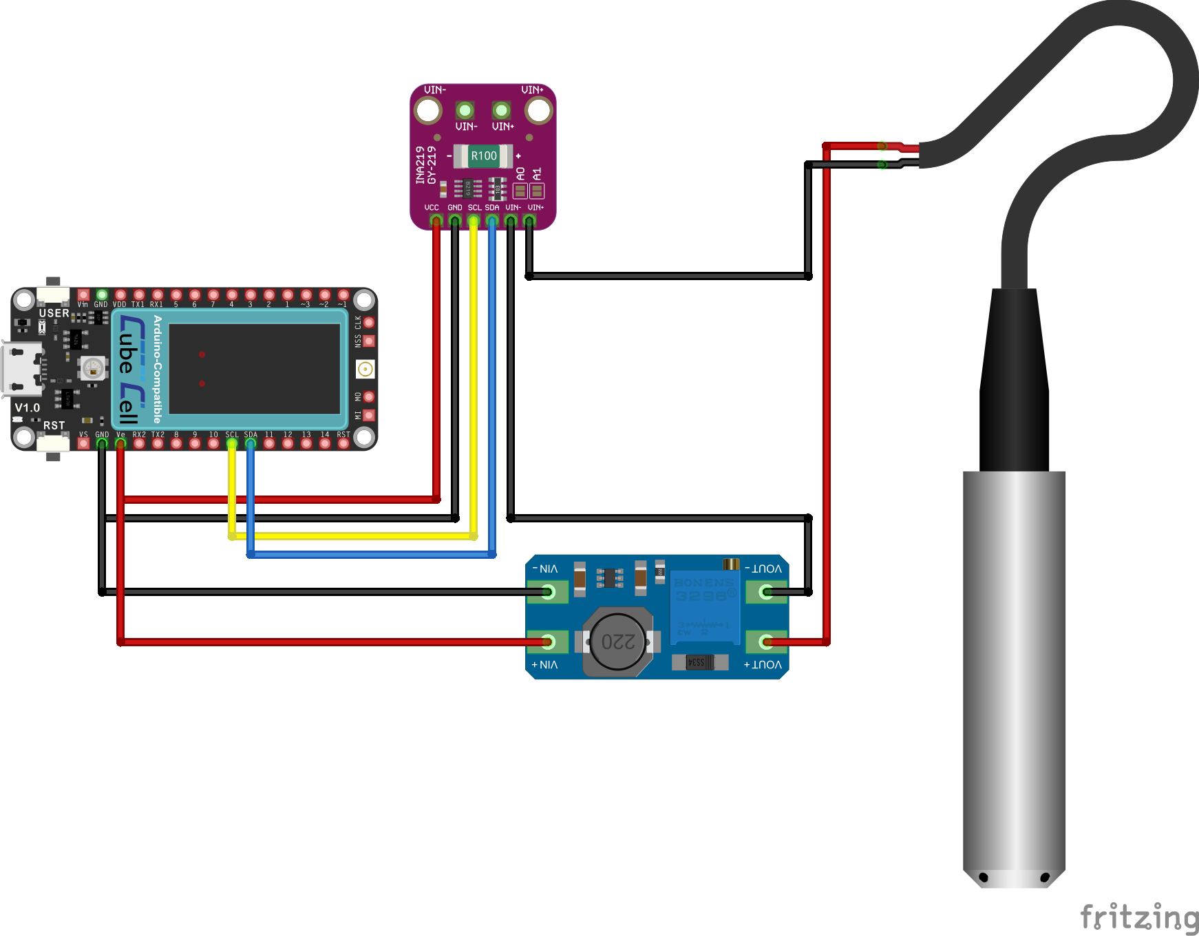
CubeCell Plus / HDL300 (2-Wire [4~20mA]) Electrical Circuit
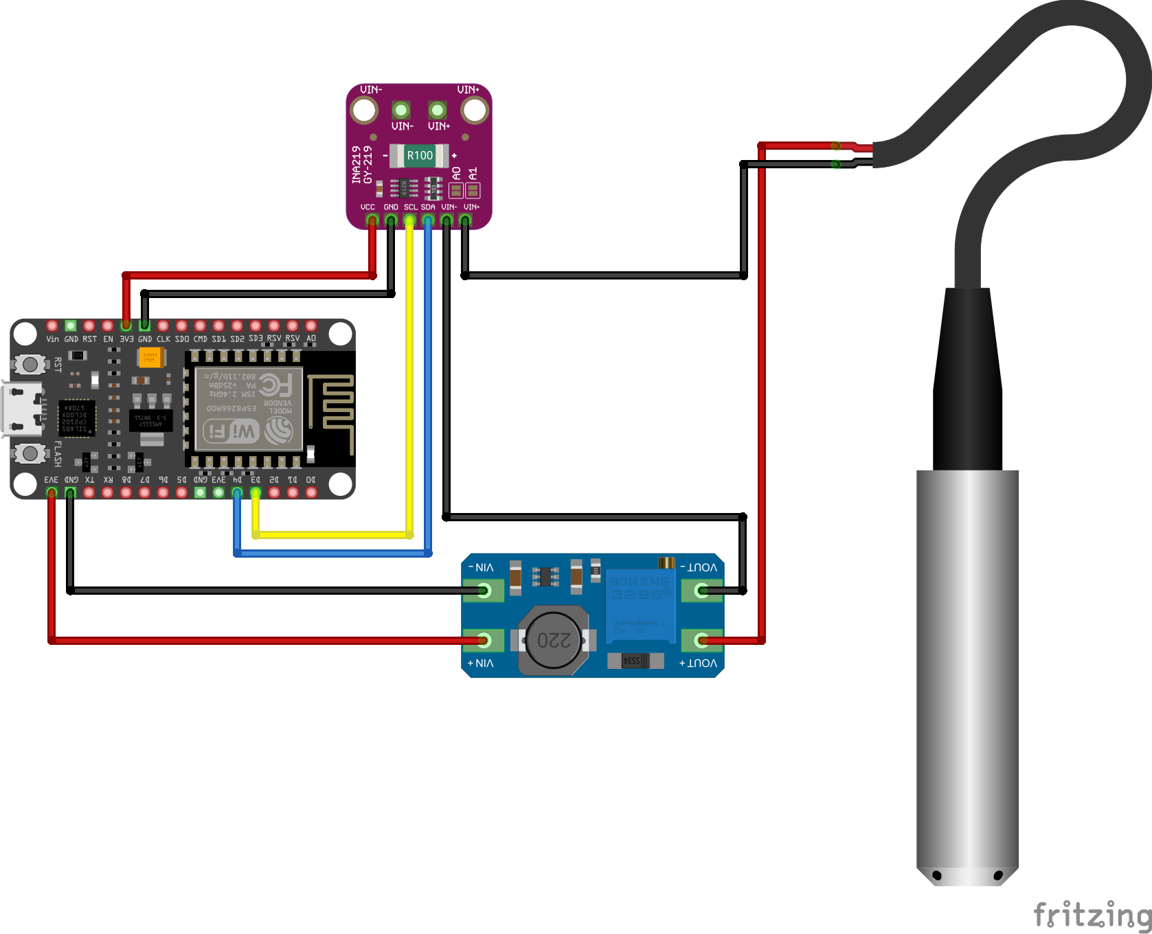
NodeMCU / HDL300 (2-Wire [4~20mA]) Electrical Circuit
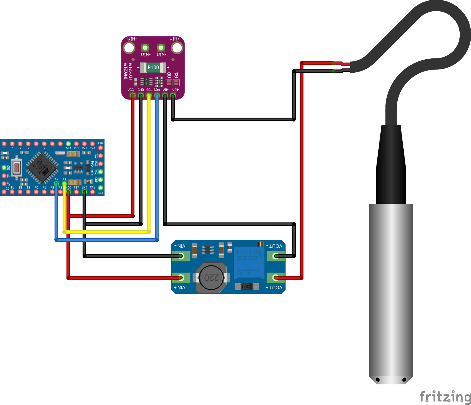
Pro Mini / HDL300 (2-Wire [4~20mA]) Electrical Circuit
Pin Configuration, as recommended by probe supplier
| CubeCell Plus |
NodeMCU |
Pro Mini |
INA219 |
Boost |
HDL300 |
| Ve |
3V3 |
ACC |
Vcc |
VIN+ |
|
| GND |
GND |
GND |
Gnd |
VIN- |
|
| SCL |
D3 |
A5 |
Scl |
|
|
| SDA |
D4 |
A4 |
Sda |
|
|
|
|
|
Vin- |
VOUT- |
|
|
|
|
Vin+ |
|
Black |
|
|
|
|
VOUT+ |
Red |
|
|
|
|
|
|
The configurations illustrated above are as recommended in the wiring diagram provided with the probe, with the current measuring device 'downstream' from the probe—the meter configured between the negative lead of the probe and ground.
The INA219 datasheet, however, notes that bus voltage measurements are made from the IN- pin relative to ground. Accordingly, if bus voltage measurements are required, the INA219 module must be configured upstream of the probe, between the power source and the positive lead of the probe, as illustrated below.
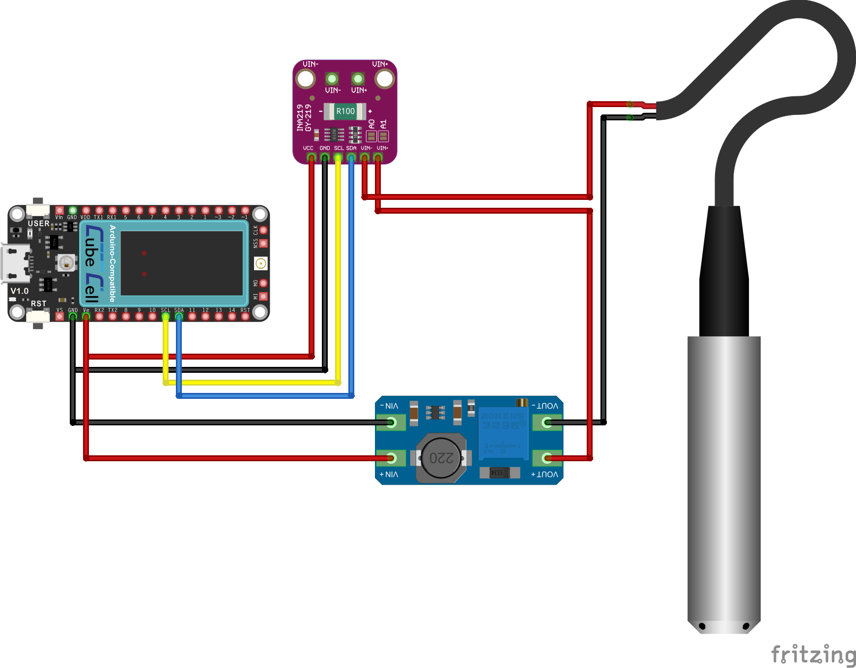
CubeCell Plus / HDL300 (2-Wire [4~20mA]) 'High Side' Electrical Circuit
Pin Configuration, if bus voltage measurement required
| CubeCell Plus |
NodeMCU |
Pro Mini |
INA219 |
Boost |
HDL300 |
| Ve |
3V3 |
ACC |
Vcc |
VIN+ |
|
| GND |
GND |
GND |
Gnd |
VIN- |
|
| SCL |
D3 |
A5 |
Scl |
|
|
| SDA |
D4 |
A4 |
Sda |
|
|
|
|
|
Vin- |
|
Red |
|
|
|
Vin+ |
VOUT+ |
|
|
|
|
|
VOUT- |
Black |
|
|
|
|
|
|
3-Wire [5V, 0~3.3V] Configuration
There are actually several versions of the 3-wire probe. Most recommend a nominal 24V operating voltage and return a signal in either the 0~5V or 0~10V range. There are, however, also versions that operate on a 5V supply and return a signal in either the 0~3.3V or 0.5~4.5V range.
I have just received one of the [5V, 0~3.3V] 3-wire [QDY30A] probes and I will add the applicable and relevant operational details as I work through the configuration and deployment process. Note once again that, while the physical appearance of the various probes—HDL300, QDY30A etc.—varies, they are all electrically equivalent.
![CubeCell Dev-Board Plus / QDY30A [0~3.3V] Hardware Configuration](../arduino/content/images/iot/software/CubeCellPlus-QDY30A_3-Wire.png)
CubeCell Plus / QDY30A (3-Wire [0~3.3V]) Electrical Circuit
The CubeCell [12 bit] ADC only accepts input in the range 0~2.4V, so a [100kΩ/220kΩ] voltage divider is required to scale back the probe's 0~3.3V range.
![Arduino Pro Mini / QDY30A [0~3.3V] Hardware Configuration](../arduino/content/images/iot/software/ProMini-QDY30A_3-Wire.png)
Pro Mini / QDY30A (3-Wire [0~3.3V]) Electrical Circuit
The Pro Mini [10 bit] ADC accepts input in the range 0~3.3V, so no voltage divider is required in this case.
![WiFi LoRa 32 / QDY30A [0~3.3V] Hardware Configuration](../arduino/content/images/iot/software/WiFiLoRa32-QDY30A_3-Wire.png)
WiFi LoRa 32 / QDY30A (3-Wire [0~3.3V]) Electrical Circuit
The WifI LoRa 32 [12 bit] ADC also accepts input in the range 0~3.3V, so, once again, no voltage divider is required.
Pin Configuration
| CubeCell Plus |
Pro Mini |
WiFi LoRa 32 |
Boost |
QDY30A |
| Ve |
ACC |
3V3 |
VIN+ |
|
| GND |
GND |
GND |
VIN- |
|
|
|
|
VOUT+ |
Red |
| ADC2 |
A1 |
GPIO47 |
|
Yellow |
|
|
|
VOUT- |
Black |
|
|
|
|
|
4-Wire [24V, RS485] Configuration
Configuration of the RS485 version of this probe is discussed in the relevant RS485 Interface page elsewhere on this website.
Software
2-Wire Configuration
There are several variables that need to be injected into our water level calculations. In the present case, our tank is 2.05m high (from inlet to overflow), we are using a [2-wire] probe that measures depth in the range 0~5m and provides output as a current in the range 4~20mA:
| Tank Height | `H_t` | `=` | 2050 | (mm) |
| Maximum Measurable Height | `H_max` | `=` | 5000 | (mm) |
| Minimum Probe Current | `I_0` | `=` | 400 | (mA x 100) |
| Maximum Probe Current | `I_max` | `=` | 2000 | (mA x 100) |
These probes are supplied calibrated for various water depths—I have seen advertisements for probes calibrated anywhere from 1m to 50m. My tanks are all between two and three metres high, but the first probe that I purchased, because I didn't know any better at the time, was one calibrated for a depth of 5m. Given what I now know, even though the 5m probe has proven adequate, I would use a 3m probe by preference in an environment like mine.
Whatever the details, once we have this information, we can proceed to calculate the water level in the tank:
-
Calculate the expected current at 100% tank capacity (mA x 100):
`I_100 = I_0 + H_t/H_max times (I_max - I_0)`
-
Record the current generated by the probe:
`I = "Measured Current"`
-
Calculate the water level as a percentage of the maximum:
`%"Full" = 100 times (I - I_0)/(I_100 - I_0)`
Under normal circumstances, these calculations will be performed independently of any remote Node. A Tank Node will simply be sending current measurements to the host processor responsible for integrating this information into its data records and/or displays. This then allows us to use a generic Tank Node configuration, one that can be used with any tank or probe. Since we will always know the source of any data packet, specific configuration details, such as the tank heights or probe measurement ranges, can be maintained on the recipient host and used in calculations as required.
Tillaart INA219 Library
I have used the Rob Tillaart INA219 library in the following sketch, rather than the AdaFruit library that appears to be more commonly used, because it provides greater configuration flexibility.
The commonly available INA219 modules, like that used in the present application, come preconfigured with a 0.1Ω shunt resistor. This configuration is more suited to measuring currents in the Amp, rather than milliAmp range applicable in a 4-20 mA current loop application. As a result, the most sensitive setting available on these modules measures across a ±400 millAmp range, with an accuracy of 0.1mA. This is not really ideal when all we are measuring is something in the 4~20mA range.
This problem is further exacerbated when using a 5m probe in a 3m tank (as was the case in the present tests), where we are ultimately reduced to an accuracy of only ~1%—not quite as good as I'd like. However, given that the present application has only been required to make decisions—when to signal a requirement to pump water between tanks—with this level of accuracy, this solution has proven workable. The fact that the Tillaart library allows the user to take advantage of the INA219 IC's ability to take average readings helps in this regard. Of course, we could do the averaging ourselves, but letting the INA219 do this itself is very much more straightforward, not least because we then do not need to be checking or waiting between measurements to be sure that a new measurement is available every time we sample.
The following is the sketch used to test the Arduino Pro Mini configuration illustrated above.
/*
	 Pro Mini INA219 Test

   Function:
   Test the function of the INA219 module in conjunction with a water level probe

   Description:
   1. Reads current (water level probe pressure, 4~20mA version) from INA219.

   20 Feb 2026 1.0.0  Initial implementation

   Digital Concepts
   20 Feb 2026
   digitalconcepts.net.au
 */
#include <Wire.h>             // I2C bus
#include <INA219.h>           // Tillaart INA219 library
#include "ProMiniPins.h"	    // Pro Mini Pin Definitions

// Define INA219 sensor
INA219 ina219(0x40);

float shuntvoltage = 0.00;
float busvoltage = 0.00;
float current_mA = 0.00;
float loadvoltage = 0.00;
float power_mW = 0.00;

void setup() {
  Serial.begin(115200);
  while (!Serial);        // Wait for serial line to become active
  Serial.println("[setup] Pro Mini [I2C] INA219/HDL300 Test");
  Serial.println();

  Wire.begin();
  Serial.println(F("[setup] Initialise INA219..."));
  if (!ina219.begin()) {
    Serial.println("[setup] Failed to find INA219 module");
    while (true);					// Twiddle your thumbs, no point proceeding...
  }
  // Bus voltage range can be 16 or 32 only
  ina219.setBusVoltageRange(16);
  // Gain can be 1, 2, 4, 8 (lower gain, higher sensitivity)
  ina219.setGain(1);
  // Average over 1..128 samples on powers of 2 steps [0..7] (4 => 16 samples)
  ina219.setBusSamples(4);
  // Average over 1..128 samples on powers of 2 steps [0..7] (4 => 16 samples)
  ina219.setShuntSamples(4);
  // Max current 400mA (minimum for module configuration), shunt resistance 0.1ohm
  ina219.setMaxCurrentShunt(0.4, 0.1);

  Serial.print(F("[setup] Bus Voltage Range: "));
  Serial.println(ina219.getBusVoltageRange());
  Serial.print(F("[setup]              Gain: "));
  Serial.println(ina219.getGain());
  // For ADC configuration register settings see INA219 Datasheet p.20, Table 5
  Serial.print(F("[setup]           Bus ADC: "));
  Serial.println(ina219.getBusADC(),BIN);
  Serial.print(F("[setup]         Shunt ADC: "));
  Serial.println(ina219.getShuntADC(),BIN);
  Serial.println();

  Serial.println(F("[setup] Set-up Complete"));
  Serial.println();
}

void loop() {
  readCurrent();
  delay(5000);
}

void readCurrent() {
  Serial.println("[readCurrent] Sensor read...");
  // Conversion flag will be set [1] if new data is available (should be 1)
  Serial.print("              Conversion Flag: "); Serial.println(ina219.getConversionFlag());
  // Overflow flag will be set [1] in case of mathematical error (should be 0)
  Serial.print("                Overflow Flag: "); Serial.println(ina219.getMathOverflowFlag());

  busvoltage = ina219.getBusVoltage();
  shuntvoltage = ina219.getShuntVoltage_mV();
  current_mA = ina219.getCurrent_mA();
  power_mW = ina219.getPower_mW();
  loadvoltage = busvoltage + (shuntvoltage / 1000);
  Serial.print("                  Bus Voltage: "); Serial.print(busvoltage); Serial.println(" V");
  Serial.print("                Shunt Voltage: "); Serial.print(shuntvoltage); Serial.println(" mV");
  Serial.print("                 Load Voltage: "); Serial.print(loadvoltage); Serial.println(" V");
  Serial.print("                      Current: "); Serial.print(current_mA); Serial.println(" mA");
  Serial.print("                        Power: "); Serial.print(power_mW); Serial.println(" mW");
  Serial.println();
}
|
Application Sketch
The following is the Arduino Pro Mini application sketch for a Tank Node that employs a 4~20mA version of an HDL300 compatible probe to measure water depth. The sketch forwards the 'raw' output from the INA219 to a LoRa Gateway Node that then sends relevant MQTT messages to the Node-RED host responsible for displaying the data. As with all of my Nodes, the Tank Node also forwards battery voltage level and enclosure temperature data.
The LoRa915.h file can be downloaded from the Software > LoRa page and the EepromHandler and PacketHandler libraries can be downloaded from the respective downloads pages (EepromHandler Downloads and PacketHandler Downloads).
The following probably needs to be augmented to illustrate the [albeit minor] variations used in support of the different processors.
ProMiniTankLevelTillaart.ino
/*
	 Pro Mini Tank Water Level Monitoring Node

   Function:
   Read local battery voltage, DS18B20 temperature sensor and water level probe data and
   forward to LoRa Gateway

   Description:
   1. Reads temperature data from onboad battery voltage measurement circuitry, DS18B20
      temperature sensor and current (water level probe pressure, 4~20mA version) from INA219.
   2. Communicates data to [Heltec WiFi LoRa 32 / Raspberry Pi] LoRa Gateway
   3. Uses EEPROM [configuration data] structures defined in the EepromHandler library
   4. Uses packet structures defined in the PacketHandler library

   2 Mar 2026 0.1.0  Initial implementation

   Digital Concepts
   2 Mar 2026
   digitalconcepts.net.au
 */

#include <LowPower.h>           // Low Power library
#include <SPI.h>                // SPI Interface for RFM95
#include <LoRa.h>               // LoRa library
#include <Wire.h>             	// I2C bus
#include <INA219.h>             // Tillaart INA219 library
#include <OneWire.h>            // DS18B20 bus
#include <DallasTemperature.h>  // DS18B20 library

#include "ProMiniPins.h"	      // Pro Mini Pin Definitions
#include "LoRa915.h"            // LoRa configuration parameters
#include "PacketHandler.h"      // Packet structures
#include "EepromHandler.h"      // EEPROM management

#define batteryMonitor  A4a_A0  // ADC
#define wakeControl     A4a_A1  // Battery monitor circuit
#define timerDone       A4a_A3  // TPL5111 timer signal

// DS18B20
#define ONE_WIRE_BUS A4a_A2
#define TEMPERATURE_PRECISION 9

struct softwareRevision {
  const uint8_t major;			// Major feature release
  const uint8_t minor;			// Minor feature enhancement release
  const uint8_t minimus;		// 'Bug fix' release
};

softwareRevision sketchRevision = {0,1,0};
String sketchRev = String(sketchRevision.major) + "." + String(sketchRevision.minor) + "." + String(sketchRevision.minimus);

// EEPROM structure
EepromHandler eeprom;

// Packet structure
PacketHandler packet;

const uint8_t batterySensorId = 1;

// Setup a oneWire instance to communicate with any OneWire devices (not just Maxim/Dallas temperature ICs)
OneWire oneWire(ONE_WIRE_BUS);

// Pass our oneWire reference to Dallas Temperature.
DallasTemperature ds18b20Sensor(&oneWire);
const uint8_t ds18b20SensorId = 2;

int16_t nodeTemperature = 0;

// Define INA219 sensor
INA219 ina219(0x40);
const uint8_t ina219SensorId = 3;

float shuntvoltage = 0.00;
float busvoltage = 0.00;
float current_mA = 0.00;
float loadvoltage = 0.00;
float power_mW = 0.00;

const int reportInterval = 60000;             // Report values every 60000 milliseconds (60 seconds)
const int sleepCycles = 8;   // Can only sleep for 8 seconds at a time

uint8_t* descriptor;
uint16_t messageCounter = 0;

void setup() {
  Serial.begin(115200);
  while (!Serial);        // If just the the basic function, must connect to a computer
    delay(100);

  Serial.println(F("[setup] HDL300 Probe [I2C INA219] Node"));
  Serial.println();

  pinMode(Builtin_LED,OUTPUT);     // Will use LED to signal packet transmission
  digitalWrite(Builtin_LED, HIGH);  // Turn it off to begin with (although, I don't know why HIGH is off...

  pinMode(timerDone, OUTPUT);          // Output signal to control TPL5111 timer
  digitalWrite(timerDone, LOW);        // Set the initial state to 'Off'

  Wire.begin();
  Wire.setClock(400000);
  eeprom.begin(&Wire);
  eeprom.setSmartSerial(false);

  Serial.print(F("[setup] Initialising "));
  descriptor = eeprom.readBytes(EH_DESCRIPTOR);
  int byteCount = eeprom.getParameterByteCount(EH_DESCRIPTOR);
  for (int i = 0; i < byteCount; i++) {
    Serial.print((char)descriptor[i]);
  }
  Serial.println(F("..."));
  Serial.println();
  Serial.println("[setup]        Sketch " + sketchRev);
  Serial.println("[setup] PacketHandler " + packet.softwareRevision(PACKET_HANDLER));
  Serial.println("[setup]   NodeHandler " + packet.softwareRevision(NODE_HANDLER));
  Serial.println("[setup] EepromHandler " + eeprom.softwareRevision());
  Serial.println();

//  Initialise the RFM95 radio
//  SPI.begin(SCK,MISO,MOSI,NSS);
  LoRa.setPins(NSS, RST, DIO0);
  Serial.println(F("[setup] Activate LoRa Sender"));
//  if (!LoRa.begin(BAND, PABOOST)) {
  if (!LoRa.begin(BAND)) {
    Serial.println(F("[setup] Starting LoRa failed!"));
    while (true);
  }

  Serial.print(F("[setup] LoRa Frequency: "));
  Serial.println(BAND);

  LoRa.setSpreadingFactor(SpreadingFactor);
  LoRa.setSignalBandwidth(SignalBandwidth);
  LoRa.setPreambleLength(PreambleLength);
  LoRa.setCodingRate4(CodingRateDenominator);
  LoRa.setSyncWord(SyncWord);
  LoRa.disableCrc();

  Serial.println(F("[setup] LoRa initialisation complete"));
  Serial.println();

  messageCounter = eeprom.readUint16(EH_SEQUENCE);

  // initialise the Packet Handler
  packet.begin(eeprom.readUint32(EH_GATEWAY_MAC),eeprom.readUint32(EH_NODE_MAC));

  // Initialize the INA219 (note that prior definition of the SDA & SCL pins is required)
  Serial.println(F("[setup] Initialise INA219..."));
  if (!ina219.begin()) {
    Serial.println(F("[setup] Failed to find INA219 module"));
    while (true);					// Twiddle your thumbs, no point proceeding...
  }
  // Bus voltage range can be 16 or 32 only
  ina219.setBusVoltageRange(16);
  // Gain can be 1, 2, 4, 8 (lower gain, higher sensitivity)
  ina219.setGain(1);
  // Average over 1..128 samples on powers of 2 steps [0..7] (4 => 16 samples)
  ina219.setBusSamples(4);
  // Average over 1..128 samples on powers of 2 steps [0..7] (4 => 16 samples)
  ina219.setShuntSamples(4);
  // Max current 400mA (minimum for module configuration), shunt resistance 0.1ohm
  ina219.setMaxCurrentShunt(0.4, 0.1);

  Serial.print(F("[setup] Bus Voltage Range: "));
  Serial.println(ina219.getBusVoltageRange());
  Serial.print(F("[setup]              Gain: "));
  Serial.println(ina219.getGain());
  // For ADC configuration register settings see INA219 Datasheet p.20, Table 5
  Serial.print(F("[setup]           Bus ADC: "));
  Serial.println(ina219.getBusADC(),BIN);
  Serial.print(F("[setup]         Shunt ADC: "));
  Serial.println(ina219.getShuntADC(),BIN);
  Serial.println();

  Serial.println(F("[setup] Set-up Complete"));
  Serial.println();
}

void loop() {
  Serial.println(F("[loop] Send Messages"));
  Serial.println();

  messageCounter++;
  packet.setSequenceNumber(messageCounter);
  packet.setPacketType(VOLTAGE);
  packet.setSensorId(batterySensorId);
  packet.setVoltage(getBatteryVoltage());
//  packet.hexDump();
  packet.serialOut();
  Serial.println();
  sendMessage();
  // Have a snooze while the gateway porocesses that one
  LowPower.powerDown(SLEEP_1S, ADC_OFF, BOD_OFF);

  messageCounter++;
  packet.setSequenceNumber(messageCounter);
  packet.setPacketType(TEMPERATURE);
  packet.setSensorId(ds18b20SensorId);

  packet.setTemperature(readDS18B20Sensor());
//  packet.hexDump();
  packet.serialOut();
  Serial.println();
  sendMessage();
  // Have a snooze while the gateway porocesses that one
  LowPower.powerDown(SLEEP_1S, ADC_OFF, BOD_OFF);

  messageCounter++;
  packet.setSequenceNumber(messageCounter);

  packet.setPacketType(TANK);
  packet.setSensorId(ina219SensorId);
  packet.setTankLevel(readCurrent());
//  packet.hexDump();
  packet.serialOut();
  Serial.println();
  sendMessage();

  eeprom.writeUint16(EH_SEQUENCE, messageCounter); // Save the message counter

//  Trigger the TPL5111 timer
  digitalWrite(timerDone, HIGH);

//  If the timer is triggered, we should never get here...
//  It seems that 8s is the longest sleep so, if we are still here, we need to loop to get to 5 min

  for ( int i = 0; i < sleepCycles; ++i ) {
//    Serial.print("[loop] Sleep cycle ");
//    Serial.println(i);
    LowPower.powerDown(SLEEP_8S, ADC_OFF, BOD_OFF);
  }
}

uint16_t getBatteryVoltage() {
  // ADC resolution
  const int resolution = 10;
  const int adcMax = pow(2,resolution) - 1;
  const float adcMaxVoltage = 3.3;
  // On-board voltage divider
  const int R1 = 27;
  const int R2 = 100;
  // Calibration measurements
  const float measuredVoltage = 4.160;
  const float reportedVoltage = 4.166;
  // Measured value multiplication factor
  const float factor = (adcMaxVoltage / adcMax) * ((R1 + R2)/(float)R2) * (measuredVoltage / reportedVoltage);

  float averageReading;
  uint16_t analogValue = 0;
  uint16_t voltage = 0;

  digitalWrite(wakeControl,HIGH);
  delay(500); // Wait a moment for things to settle down

  Serial.println(F("[getBatteryVoltage] Read battery voltage..."));

  // Take an average

  int averageCount = 10;
  for (int i = 0; i < averageCount; i++) {
    analogValue += analogRead(batteryMonitor);
    delay(10);
  }
  averageReading = analogValue / (float)averageCount;

  Serial.print(F("          Average ["));
  Serial.print(averageCount);
  Serial.print(F("] ADC reading: "));
  Serial.println(averageReading);

  digitalWrite(wakeControl,LOW);
  voltage = (uint16_t)(averageReading * factor * 1000); // milliVolts
  Serial.print(F("                           Voltage: "));
  Serial.print(voltage);
  Serial.println(" mV");

  return voltage;
}

int16_t readDS18B20Sensor() {
  int16_t temperature = 0;
//  Serial.println("[readDS18B20Sensor] Read sensor...");
  ds18b20Sensor.requestTemperatures(); // Send the command to get temperatures

  // After we get the temperature(s), we can print it/them here.
  // We use the function ByIndex and get the temperature from the first sensor (there's only one at the moment).
//  Serial.println("[readDS18B20Sensor] Device 1 (index 0)");
  float sensorValue = ds18b20Sensor.getTempCByIndex(0);
//  Serial.print("[readDS18B20Sensor] Returned value: ");
//  Serial.println(sensorValue);

  temperature = (int) (10*(sensorValue + 0.05));  // °C x 10
  Serial.print("[readDS18B20Sensor] Temperature: ");
  Serial.println((float) temperature/10, 1);

  return temperature;
}

uint16_t readCurrent(void) {
  Serial.println("[readCurrent] Sensor read...");
  Serial.print("              Conversion Flag: "); Serial.println(ina219.getConversionFlag());
  Serial.print("                Overflow Flag: "); Serial.println(ina219.getMathOverflowFlag());

  busvoltage = ina219.getBusVoltage();
  shuntvoltage = ina219.getShuntVoltage_mV();
  current_mA = ina219.getCurrent_mA();
  power_mW = ina219.getPower_mW();
  loadvoltage = busvoltage + (shuntvoltage / 1000);
  Serial.print("                  Bus Voltage: "); Serial.print(busvoltage); Serial.println(" V");
  Serial.print("                Shunt Voltage: "); Serial.print(shuntvoltage); Serial.println(" mV");
  Serial.print("                 Load Voltage: "); Serial.print(loadvoltage); Serial.println(" V");
  Serial.print("                      Current: "); Serial.print(current_mA); Serial.println(" mA");
  Serial.print("                        Power: "); Serial.print(power_mW); Serial.println(" mW");

  return (uint16_t)(current_mA * 100 + 0.5);
}

void sendMessage() {
// If the host is little endian, we need to reverse the byte order before sending

//  Serial.println(F("[sendMessage] Sending packet: "));
  digitalWrite(Builtin_LED, LOW);  // Turn on the LED to signal sending
/*
// Check that no one else is transmitting first
  while ((bool) LoRa.available()) {
    Serial.println("[sendMessage] Busy...");
// It would take 212 ms to transmit a [max size] 255 byte packet at 9600 bps
    delay(random(200));
  }
*/
  LoRa.beginPacket();             // start packet
  LoRa.write((uint8_t *)packet.byteStream(), packet.packetByteCount());    // Load the output buffer
//  Serial.println("[sendMessage] Finished Packet");
  LoRa.endPacket();             // Finish packet and send it
//  Serial.println(F("[sendMessage] Packet Sent"));
  digitalWrite(Builtin_LED, HIGH);  // Done
//  Serial.println();
}
|
3-Wire Configuration
The variables that need to be injected into our water level calculations in this case are similar to those used in the 2-wire case. In the following example, we use the same 2.05m high tank but in this case we are using a [3-wire] probe that measures depth in the range 0~3m and provides output as a voltage in the range 0~3.3V:
| Tank Height | `H_t` | `=` | 2050 | (mm) |
| Maximum Measurable Height | `H_max` | `=` | 3000 | (mm) |
| Minimum Signal Voltage | `V_0` | `=` | 0 | (mV) |
| Maximum Signal Voltage | `V_max` | `=` | 3300 | (mV) |
To calculate the water level in the tank:
-
Calculate the expected voltage at 100% tank capacity (mV):
`V_100 = V_0 + H_t/H_max times (V_max - V_0)`
-
Record the signal voltage generated by the probe:
`V = "Measured Voltage"`
-
Calculate the water level as a percentage of the maximum:
`%"Full" = 100 times (V - V_0)/(V_100 - V_0)`
Once again, these calculations will be performed independently of any remote Node. In this case, a Tank Node will simply be sending voltage measurements to the host processor responsible for integrating this information into its data records and/or displays.
The following is the sketch used to test the CubeCell Dev-Board Plus configuration illustrated above.
CubeCellPlusQDY30AVoltage.ino
/*
	 CubeCell Plus 3-Wire QDY30A Probe Test

   Function:
   Test the function of a 3-Wire QDY30A water level probe with a CubeCell Dev-Board Plus

   Description:
   1. Reads voltage (water level probe pressure, 0~3.3V signal) from ADC2 and calculates
   		tank water level.

   13 Apr 2026 1.0.0  Initial implementation

   Digital Concepts
   13 Apr 2026
   digitalconcepts.net.au
*/

#include <HT_SH1107Wire.h>    // CubeCell Plus display library

#define SIGNAL_PIN ADC2       // probe signal wire connection

unsigned long reportPeriod_msec = 5000;        // Report period in msec

uint16_t adcReading;
uint16_t signalVoltage;

uint16_t tankHeight = 2050;
uint16_t probeDepthRange = 3000;
uint16_t probeVoltageRange = 3300;
uint16_t signalVoltageOffset = 0;
uint16_t baseSignalVoltage = 2;		// Reported value with probe in free air
uint16_t maxSignalVoltage = baseSignalVoltage + uint16_t((((float)tankHeight/probeDepthRange) * probeVoltageRange));
uint16_t signalVoltageRange = maxSignalVoltage - baseSignalVoltage;
uint8_t waterLevel = 0;   // Will be calculated as a percentage of tank capacity

  // CubeCell ADC resolution
  const int resolution = 12;
  const int adcMax = pow(2,resolution) - 1;
  const float adcMaxVoltage = 2.4;
  // Voltage divider - The following brings a 3.5V signal back to 2.4V at the ADC
  const int R1 = 100;
  const int R2 = 220;
  // Calibration measurements (not used in this case)
  const float measuredVoltage = 3.3;
  const float reportedVoltage = 3.3;
  // Calibration factor
  const float calibrationFactor = (adcMaxVoltage / adcMax) * ((R1 + R2)/(float)R2) * (measuredVoltage / reportedVoltage);

SH1107Wire  boardDisplay(0x3c, 500000, SDA, SCL, GEOMETRY_128_64, GPIO10), *displayPtr; // addr, freq, sda, scl, resolution, rst

void setup() {
  Serial.begin(115200);

  pinMode(Vext, OUTPUT);    // Sensor (boost converter) power
  digitalWrite(Vext, LOW);  // Activate Vext (we're really writing to Vext_Ctrl here)
  pinMode(ADC2, INPUT);     // probe anlaog input

  boardDisplay.init();
  boardDisplay.setFont(ArialMT_Plain_10);
  boardDisplay.screenRotate(ANGLE_180_DEGREE);

  boardDisplay.clear();
  boardDisplay.setFont(ArialMT_Plain_10);
  boardDisplay.setTextAlignment(TEXT_ALIGN_LEFT);
  boardDisplay.drawString(5,0,"QDY30A Sensor");
  boardDisplay.display();
  delay(1000);
}

void loop() {
  adcReading = analogRead(SIGNAL_PIN);
  signalVoltage = uint16_t(1000.0 * adcReading * calibrationFactor);
  waterLevel = int(100 * signalVoltage / signalVoltageRange);

  Serial.print("[loop] adcReading : ");
  Serial.println(adcReading);
  Serial.print("[loop] signalVoltage : ");
  Serial.println(signalVoltage);
  Serial.print("[loop] baseSignalVoltage : ");
  Serial.println(baseSignalVoltage);
  Serial.print("[loop] maxSignalVoltage : ");
  Serial.println(maxSignalVoltage);
  Serial.print("[loop] signalVoltageRange : ");
  Serial.println(signalVoltageRange);
  Serial.print("[loop] waterLevel : ");
  Serial.println(waterLevel);

  boardDisplay.clear();
  boardDisplay.setFont(ArialMT_Plain_10);
  boardDisplay.setTextAlignment(TEXT_ALIGN_LEFT);
  boardDisplay.drawString(5,10,"QDY30A");

  boardDisplay.setTextAlignment(TEXT_ALIGN_RIGHT);
  boardDisplay.drawString(45,20,"ADC");
  boardDisplay.drawString(45,30,"Voltage");
  boardDisplay.drawString(45,40,"Level");

  boardDisplay.setTextAlignment(TEXT_ALIGN_LEFT);
  boardDisplay.drawString(55,20,String(adcReading));
  boardDisplay.drawString(55,30,String(signalVoltage) + "mV");
  boardDisplay.drawString(55,40,String(waterLevel) + "%");

  boardDisplay.display();

  Serial.print(reportPeriod_msec/1000);
  Serial.println(" second pause..");
  Serial.println();
  delay(reportPeriod_msec);
}
|
Application Sketch
The application sketch in this case only differs from that of the 2-wire probe in the way the probe signal is read. In this case, it is a voltage rather than a current measurement that is sent to the Node-RED host. It will be up to the host to note the type of probe in use and to then perform the necessary calculation to determine the water level in the tank.
From v1.1.0 of the PacketHandler library, the TANK packet structure and associated MQTT message topic have been augmented to include the sensor type. This obviates any need for the Node-RED host to retain this information.
4-Wire Configuration
The 4-wire configuration is discussed in the section dedicated to the discussion of the RS485 interface.

