

QDY30A Water Level [Pressure] Sensor
![QDY30A-B Water Level [Pressure] Sensor](../arduino/content/images/iot/assembly/sensors/QDY30A-B.jpg)
This type of water level/pressure sensor comes in several variations, differing in the way in which readings are made—via a current loop (4~20mA), a voltage (0~3.3V or 0~5V) or an RS485 interface. The present example deals with the [4-wire] RS485 version. Configuration of the [2‑wire] current loop and [3-wire] voltage versions are discussed elsewhere on this site.
To date, I have used the manual for a similar sensor, retrieved from the ComWinTop website, as a guide in forumlating the necessary Modbus RTU queries.
Testing Notes
- The sensor specifications indicate that it requires a 24V supply—this is what is inscribed on the sensor that I have—but will operate with a supply voltage of 12~36V. Based on comments that some variants of these sensors would operate on a 5V supply, I hooked it up to the 5V
Vinpin on the CubeCell Plus Dev-Board and it all seems to work. I have read one report that indicated problems with a similar [QDY30A] sensor, but not with an RS485 interface, when operating at 12V, even though the specs suggested that 12V~36V should be OK. In the present case, however, the RS485 probe, operating at 5V, is consistently reporting the same levels as a [0~3.3V] 3-wire probe I have in the same tank. - Supplied with a default baud rate setting of 9600.
- Responds to a Modbus RTU broadcast address of
0x00. - As supplied, when queried this sensor reports a Slave ID of
0x01. It will respond to queries directed either to this address or the broadcast address. Like the SHT30 sensor, the Water Level sensor would not comply with any attempt to change its Slave ID, although it did correctly report its Slave ID of0x01when so queried. Once again, it may be that I am doing something wrong here, but I am following the same process that I used to successfully change the Slave ID of the Soil Condition sensor.
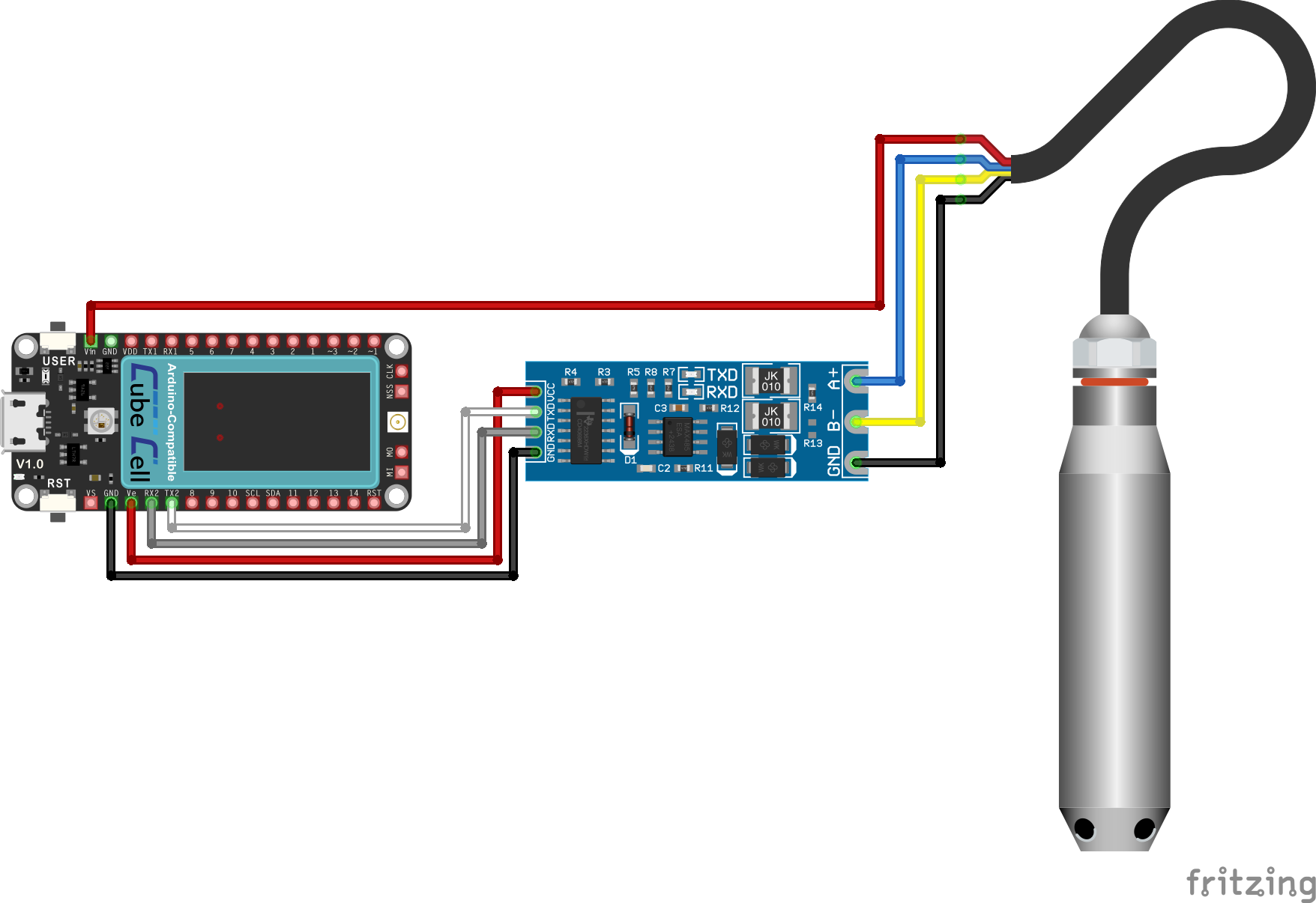
QDY30A Sensor [RS485] Configuration Circuit
Pin Configuration
| CubeCell Plus | UART-to-RS485 | QDY30A |
|---|---|---|
| GND | GND | |
| UART_TX2 | Tx | |
| UART_RX2 | Rx | |
| Vext | Vcc | |
| Vin | Red | |
| A+ | Blue | |
| B- | Yellow | |
| Sig-GND | Black |
Note that the colours of the RS485 wires on the various probes that I have tested have all been different so it is important to verify which wire is which on any given probe and not rely on any idea of standardised colouring of wires. In particular, the RS485 A+/B- signal wires are often the exact opposite of those illustrated here for the QDY30A probe—yellow and blue respectively, rather than blue and yellow. Thankfully, there has always been some form of identification, apart from colour, on the wires of RS485 probes that I have purchased—a card included with the probe or tags on relevant wires.
Software
|
Further details pending