CCS811 Air Quality Sensor
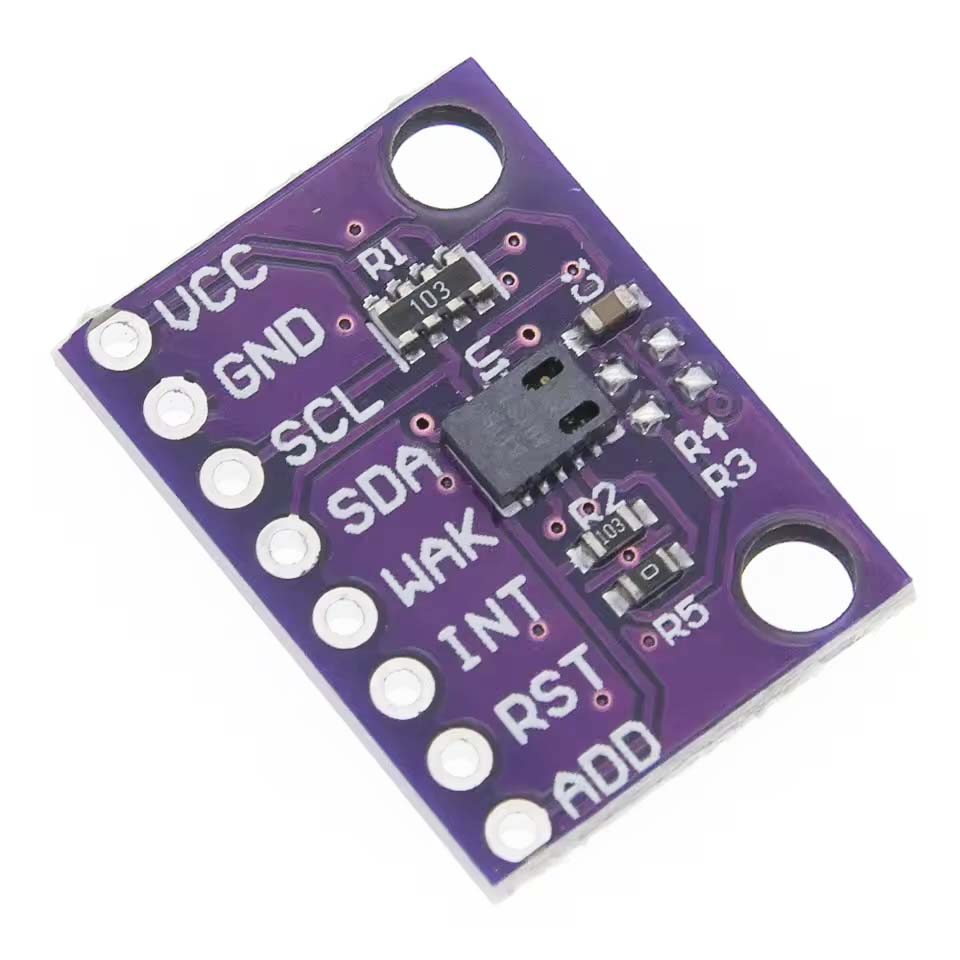
This section deals with the configuration of the CCS811 air quality sensor.
This whole page is still very much a work in progress and, at this point, not much more than a collection of other people's work. I've had problems with this particular module from the outset and I'm beginning to suspect that I've got a dud... I'll remove this comment if I ever manage to source a working module and actually produce some results of my own.
STOP PRESS [9 Sep 2025] : Persistence has won out, for what it might now be worth! I've just received my third (!) module and I finally have one that seems to work! Details, again for what they might be worth, coming soon...
Application
I had originally intended to include the CCS811 sensor in my weather station configuration. Regardless of the lack of success in my efforts to configure this sensor module, recent investigations seem to suggest that the ESN160 air quality sensor will be a better option.
There is a suggestion in the SparkFun Hookup Guide that this sensor needs to run for 20 min before it stabilises and is suitable for taking readings... The CCS811 datasheet, however, states "Warm-up Time < 15s".
There are also 'warnings' that the IC engages in I2C clock stretching and is thus incompatible with some processors (see DFRobot Wiki).
Configuration
The DFRobot wiki page on its CS811 module provides a good overview of this sensor and its configuration requirements.
From the How 2 Electronics website:
Features of CCS811 Gas Sensor
- Integrated MCU
- Operating Voltage: 1.8V to 3.6V
- On-board processing
- A standard I²C digital interface with an I²C Address of 0x5A or 0X5B
- Optimized low-power modes
- Short warm-up time: < 15sec
- 2.7mm x 4.0mm x 1.1mm LGA package
- Low component count
- Proven technology platform, compact and economical
- eCO2 Measurement range: 400 to 8192ppm
- TVOC Measurement range: 0 to 1187ppb
- Multiple drive modes for measurements every 1s, 10s, 60s, or every 250ms
- Arduino and CircuitPython compatibility
- Integrated 12-bit ADC for sensor readings and digitized conversions
- Reset / interrupt control
CCS811 Pinout Configuration
- VCC – This is the power pin. The sensor uses 3.3V to power the board.
- GND – Common ground for power and logic.
- SCL – This is the I²C clock pin pulled to VCC via a 10K resistor.
- SDA – This is the I²C data pin pulled to VCC via a 10K resistor.
- WAKE – This is the wake-up pin for the sensor. It needs to be pulled to the GND in order to communicate with the sensor. Pull this line high or VCC put the sensor to sleep.
- INT – This is the interrupt-output pin. It is 3V logic and one can use it to detect when a new reading is ready or when the reading gets too high or too low.
- RST – This is the reset pin. When it is pulled to GND the sensor resets itself.
- ADD – Single address select bit to allow the alternate address to be selected. When ADDR is low the 7-bit I²C address is decimal 90 / hex 0x5A. When ADDR is high the 7-bit I²C address is decimal 91 / hex 0x5B.
CCS811 Programming Guide
DFRobot CCS811 Product Wiki.
SparkFun Hookup Guide
The following details relate to my attempts to work with this sensor module. It should be noted, however, that I am yet to be able to even detect the sensor, when configured as described below, using the I2C scanner software that I have used to verify the operation of all other I2C sensors I have tested.
Hardware
Note that the WAK pin on the sensor module must be pulled LOW to activate the sensor. This can be achieved either by physically connecting the WAK pin to GND or through appropriate software setting of a processor pin to which the WAK pin is connected.
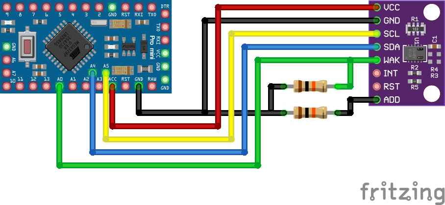
Arduino Pro Mini / CCS811 Electrical Circuit
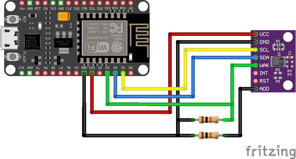
NodeMCU / CCS811 Electrical Circuit
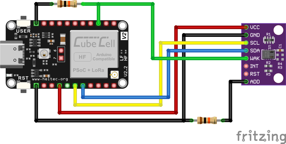
CubeCell / CCS811 Electrical Circuit
Pin Configurations
| Arduino Pro Mini |
NodeMCU |
CubeCell |
CCS811 |
| Vext |
VCC |
3V3 |
VCC |
GND |
GND |
GND |
GND |
| A5 |
D1 |
SCL |
SCL |
| A4 |
D2 |
SDA |
SDA |
| A0 (Pull-Down) |
D3 (Pull-Down) |
GPIO2 (Pull-Down) |
WAK |
|
|
|
INT |
|
|
|
RST |
| Pull-Down |
Pull-Down |
Pull-Down |
ADD |
Software
The default I2C address for the CSS812 module is 0x5A, although it can also be configured to use the I2C address 0x5B. Given that I have never yet been able to elicit a response from this module when scanning the I2C bus to which it has been connected, I cannot confirm which address is actually being used. On that basis, I cannot even confirm that the hardware configuration that I have used is correct.
With regard to the need for the WAK pin on the module to be pulled LOW in order to activate the sensor, I have tried both 'hard wiring' the pin to GND and connecting it to a processor pin that is set LOW through software without any obvious result in either case.
Starting point for a test sketch (library example sketch):
#include <ESP8266WebServer.h>
#include <Wire.h>    // I2C library
#include "ccs811.h"  // CCS811 library


// Wiring for ESP8266 NodeMCU boards: VDD to 3V3, GND to GND, SDA to D2, SCL to D1, nWAKE to D3 (or GND)
CCS811 ccs811(0); // nWAKE on D3

float val1, val2;

const char* ssid = "Trilobite II";  // Enter SSID here
const char* password = "Tr1l0b1t3";  //Enter Password here

ESP8266WebServer server(80);

void setup()
{
  // Enable serial
  Serial.begin(115200);
  Serial.println("");
  Serial.println("setup: Starting CCS811 basic demo");
  Serial.print("setup: ccs811 lib  version: ");
  Serial.println(CCS811_VERSION);

  // Enable I2C
  Wire.begin();

  // Enable CCS811
  ccs811.set_i2cdelay(50); // Needed for ESP8266 because it doesn't handle I2C clock stretch correctly
  bool ok = ccs811.begin();
  if ( !ok ) Serial.println("setup: CCS811 begin FAILED");

  // Print CCS811 versions
  Serial.print("setup: hardware    version: "); Serial.println(ccs811.hardware_version(), HEX);
  Serial.print("setup: bootloader  version: "); Serial.println(ccs811.bootloader_version(), HEX);
  Serial.print("setup: application version: "); Serial.println(ccs811.application_version(), HEX);

  // Start measuring
  ok = ccs811.start(CCS811_MODE_1SEC);
  if ( !ok ) Serial.println("setup: CCS811 start FAILED");

  Serial.println("Connecting to ");
  Serial.println(ssid);

  //connect to your local wi-fi network
  WiFi.begin(ssid, password);

  //check wi-fi is connected to wi-fi network
  while (WiFi.status() != WL_CONNECTED) {
    delay(1000);
    Serial.print(".");
  }
  Serial.println("");
  Serial.println("WiFi connected..!");
  Serial.print("Got IP: ");
  Serial.println(WiFi.localIP());

  server.on("/", handle_OnConnect);
  server.onNotFound(handle_NotFound);

  server.begin();
  Serial.println("HTTP server started");
}


void loop()
{

  // Read
  uint16_t eco2, etvoc, errstat, raw;
  ccs811.read(&eco2, &etvoc, &errstat, &raw);

  // Print measurement results based on status
  if ( errstat == CCS811_ERRSTAT_OK )
  {
    val1 = eco2;
    val2 = etvoc;

    Serial.print("CCS811: ");
    Serial.print("eco2=");
    Serial.print(val1);
    Serial.print(" ppm  ");

    Serial.print("etvoc=");
    Serial.print(val2);
    Serial.print(" ppb  ");
    Serial.println();
  }
  else if ( errstat == CCS811_ERRSTAT_OK_NODATA )
  {
    Serial.println("CCS811: waiting for (new) data");
  } else if ( errstat & CCS811_ERRSTAT_I2CFAIL )
  {
    Serial.println("CCS811: I2C error");
  }
  else
  {
    Serial.print("CCS811: errstat=");
    Serial.print(errstat, HEX);
    Serial.print("=");
    Serial.println( ccs811.errstat_str(errstat) );
  }

  // Wait
  delay(1000);
  server.handleClient();
}

void handle_OnConnect()
{

  server.send(200, "text/html", SendHTML(val1, val2));
}

void handle_NotFound()
{
  server.send(404, "text/plain", "Not found");
}

String SendHTML(float val1, float val2)
{
  String ptr = "<!DOCTYPE html> <html>\n";
  ptr += "<head><meta name=\"viewport\" content=\"width=device-width, initial-scale=1.0, user-scalable=no\">\n";
  ptr += "<title>Measured Air Quality</title>\n";
  ptr += "<style>html { font-family: Helvetica; display: inline-block; margin: 0px auto; text-align: center;}\n";
  ptr += "body{margin-top: 50px;} h1 {color: #444444;margin: 50px auto 30px;}\n";
  ptr += "p {font-size: 24px;color: #444444;margin-bottom: 10px;}\n";
  ptr += "</style>\n";
  ptr += "<script>\n";
  ptr += "setInterval(loadDoc,1000);\n";
  ptr += "function loadDoc() {\n";
  ptr += "var xhttp = new XMLHttpRequest();\n";
  ptr += "xhttp.onreadystatechange = function() {\n";
  ptr += "if (this.readyState == 4 && this.status == 200) {\n";
  ptr += "document.body.innerHTML =this.responseText}\n";
  ptr += "};\n";
  ptr += "xhttp.open(\"GET\", \"/\", true);\n";
  ptr += "xhttp.send();\n";
  ptr += "}\n";
  ptr += "</script>\n";
  ptr += "v/head>\n";
  ptr += "<body>\n";
  ptr += "<div id=\"webpage\">\n";
  ptr += "<h1>Measured Air Quality</h1>\n";

  ptr += "<p>CO2: ";
  ptr += val1;
  ptr += " ppm</p>";

  ptr += "<p>TVOC: ";
  ptr += val2;
  ptr += " ppb</p>";

  ptr += "</div>\n";
  ptr += "</body>\n";
  ptr += "</html>\n";
  return ptr;
}
|
Alternate starting point for test sketch from Sparkfun:
Arduino-Sparkfun CCS811.ino
/******************************************************************************
  Read basic CO2 and TVOCs

  Marshall Taylor @ SparkFun Electronics
  Nathan Seidle @ SparkFun Electronics

  April 4, 2017

  https://github.com/sparkfun/CCS811_Air_Quality_Breakout
  https://github.com/sparkfun/SparkFun_CCS811_Arduino_Library

  Read the TVOC and CO2 values from the SparkFun CSS811 breakout board

  A new sensor requires at 48-burn in. Once burned in a sensor requires
  20 minutes of run in before readings are considered good.

  Hardware Connections (Breakoutboard to Arduino):
  3.3V to 3.3V pin
  GND to GND pin
  SDA to A4
  SCL to A5

******************************************************************************/
#include <Wire.h>

#include "SparkFunCCS811.h" //Click here to get the library: http://librarymanager/All#SparkFun_CCS811

#define CCS811_ADDR 0x5B //Default I2C Address
//#define CCS811_ADDR 0x5A //Alternate I2C Address

CCS811 mySensor(CCS811_ADDR);

void setup()
{
  Serial.begin(115200);
  Serial.println("CCS811 Basic Example");

  Wire.begin(); //Inialize I2C Hardware

  if (mySensor.begin() == false)
  {
    Serial.print("CCS811 error. Please check wiring. Freezing...");
    while (1)
      ;
  }
}

void loop()
{
  //Check to see if data is ready with .dataAvailable()
  if (mySensor.dataAvailable())
  {
    //If so, have the sensor read and calculate the results.
    //Get them later
    mySensor.readAlgorithmResults();

    Serial.print("CO2[");
    //Returns calculated CO2 reading
    Serial.print(mySensor.getCO2());
    Serial.print("] tVOC[");
    //Returns calculated TVOC reading
    Serial.print(mySensor.getTVOC());
    Serial.print("] millis[");
    //Display the time since program start
    Serial.print(millis());
    Serial.print("]");
    Serial.println();
  }

  delay(10); //Don't spam the I2C bus
}
|
Another from the How 2 Electronics website, with output to an OLED display:
#include "Adafruit_CCS811.h"
#include <Wire.h>
#include <Adafruit_GFX.h>
#include <Adafruit_SSD1306.h>

#define SCREEN_WIDTH 128    // OLED display width, in pixels
#define SCREEN_HEIGHT 64    // OLED display height, in pixels
#define OLED_RESET -1       // Reset pin # (or -1 if sharing Arduino reset pin)
Adafruit_SSD1306 display(SCREEN_WIDTH, SCREEN_HEIGHT, &Wire, OLED_RESET);

Adafruit_CCS811 ccs;

void setup()
{
  Serial.begin(9600);
  display.begin(SSD1306_SWITCHCAPVCC, 0x3C); //initialize with the I2C addr 0x3C (128x64)
  delay(500);
  display.clearDisplay();
  display.setCursor(25, 15);
  display.setTextSize(1);
  display.setTextColor(WHITE);
  display.println("CCS811 Sensor");
  display.setCursor(25, 35);
  display.setTextSize(1);
  display.print("Initializing");
  display.display();

  Serial.println("CCS811 test");

  if (!ccs.begin())
  {
    Serial.println("Failed to start sensor! Please check your wiring.");
    while (1);
  }

  // Wait for the sensor to be ready
  while (!ccs.available());
}

void loop()
{
  if (ccs.available())
  {
    if (!ccs.readData())
    {
      Serial.print("CO2: ");
      Serial.print(ccs.geteCO2());
      Serial.print("ppm, TVOC: ");
      Serial.println(ccs.getTVOC());

      display.clearDisplay();
      display.setTextSize(1);
      display.setCursor(20, 0);
      display.print("Air Quality");

      display.setTextSize(2);
      display.setCursor(0, 20);
      display.print("CO2:");
      display.print(ccs.geteCO2());
      display.setTextSize(1);
      display.print(" ppm");

      display.setTextSize(2);
      display.setCursor(0, 45);
      display.print("TVOC:");
      display.print(ccs.getTVOC());
      display.display();
    }
    else
    {
      Serial.println("ERROR!");
      display.clearDisplay();
      display.setTextSize(2);
      display.setCursor(0, 5);
      display.print("ERROR!");
      while (1);
    }
  }
  delay(1000);
}
|
Calibration
Having now worked with the three different air quality sensors, CCS811, ENS160 and MQ-135, there is clearly a need for some level of calibration. Out of the box, the three sensors give quite different readings and I've not yet managed to come up with a setup sequence that yields an acceptable level of correlation between the three or, at least, a satisfactory explanation for the observed divergence in readings.
Further details pending

