

ENS160 Air Quality Sensor

This section deals with the configuration of the ENS160 air quality sensor. Two versions of ENS160 sensor module have been tested, a basic version that simply uses the ENS160 air quality sensor and another that also includes an AHT21 temperature and humidity sensor. Both modules are provided with I2C and SPI interfaces and can be configured to trigger an interrupt when pollutant levels exceed a preset value.
*** NOTE ***
While I have presented configuration details for both modules below, I have not been able to get the [purple] ENS160-only module to return any [non-zero] data, using either an I2C or SPI configuration. The sensor is recognised on the I2C bus, and can be successfully initialised on either bus, but only zeroes are returned in response to requests for sensor data.
The ENS160 sensor on the [blue] combo board, in contrast, returns data as expected in either configuration. The AHT21 temperature sensor, however, is only accessible via the I2C interface.
Application
An ENS160 sensor will ultimately become a component of my local weather station.
Configuration
Refer to the DFRobot Wiki and DFRobot project pages. There's a lot of good stuff there and little value in my simply regurgitating any of it here.
Hardware
While my intended application for the ENS160 sensor is based on the CubeCell-Board Plus platform, both Arduino Pro Mini and NodeMCU configurations were also tested. This was primarily to eliminate the possibility that the problems experienced with the [purple] ENS160-only module were related to the processor platform—the Wire (I2C) and SPI libraries used to communicate with the sensor are platform-specific. In the event, at the sketch level and with the aid of conditional compilation macros, the code for all platforms is practically identical, the only customisable element being the relevant processor pin specifications (see below).
I2C Bus
My original intention was to use the I2C option, but this was before I discovered that there could be a conflict between the either of I2C addresses available for the ENS160 IC (0x52 or 0x53) and those potentially used by some of the AT24Cxx EEPROMs (0x50..0x57) that I had chosen to use in my Nodes. Nonetheless, the AHT21 temperature sensor included on the [blue] ENS160+AHT21 module is only accessible via the I2C interface so, if it were to be used, an I2C configuration was going to be required.
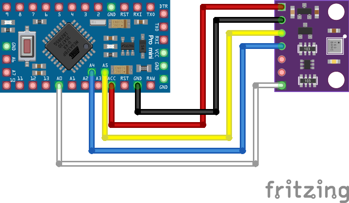
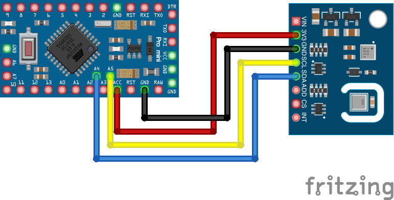
Arduino Pro Mini / ENS160 I2C Electrical Circuits
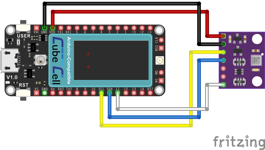
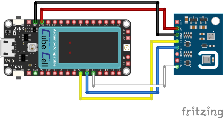
CubeCell Plus / ENS160 I2C Electrical Circuits
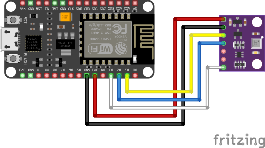
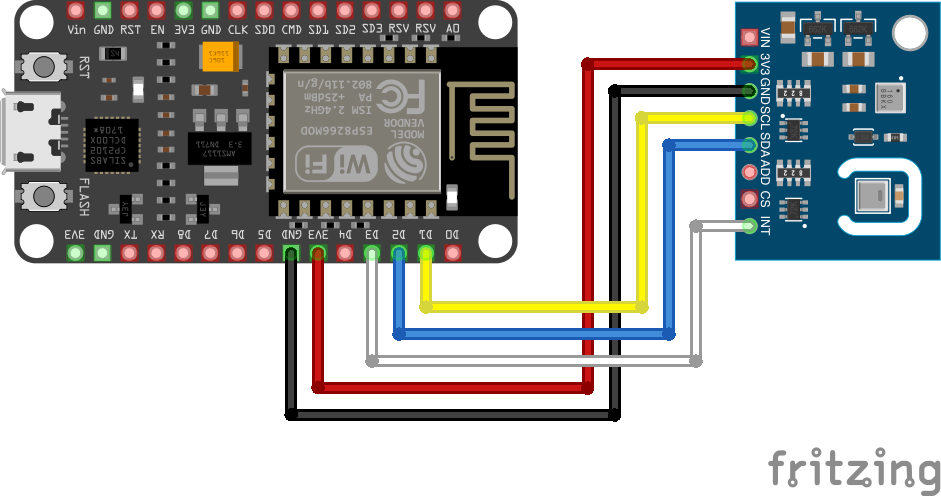
NodeMCU / ENS160 I2C Electrical Circuits
Pin Configurations
| Arduino Pro Mini | CubeCell Plus | NodeMCU | ENS160 | ENS160 + AHT21 |
|---|---|---|---|---|
| VIN | ||||
| ACC | VDD | 3V3 | 3V3 | 3V3 | GND | GND | GND | GND | GND |
| A5 | SCL | D1 | SCL | SCL |
| A4 | SDA | D2 | SDA | SDA |
| CS | CS | |||
| ADD | ADD | |||
| A0 | GPIO11 | D3 | INT | INT |
Although not included in the above illustrations, it is generally recommended to configure pull-up resistors on the I2C SDA & SCL lines. Indeed, all of my application circuits include these pull-up resistors. Nonetheless, I have found that simple tests, such as those described herein, where connections are made with relatively short (10~20cm) wires, are generally fine without them.
SPI Bus
While, as noted above, using the SPI interface option on the ESNS160 modules avoids any potential I2C address conflicts, the main reason for testing the SPI interface was to eliminate the I2C bus interface as the cause of the problems encountered with the [purple] ENS160-only module. In the event, the results were the same regardless of the processor platform or bus used.
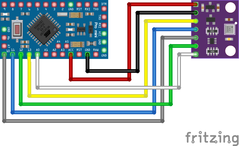
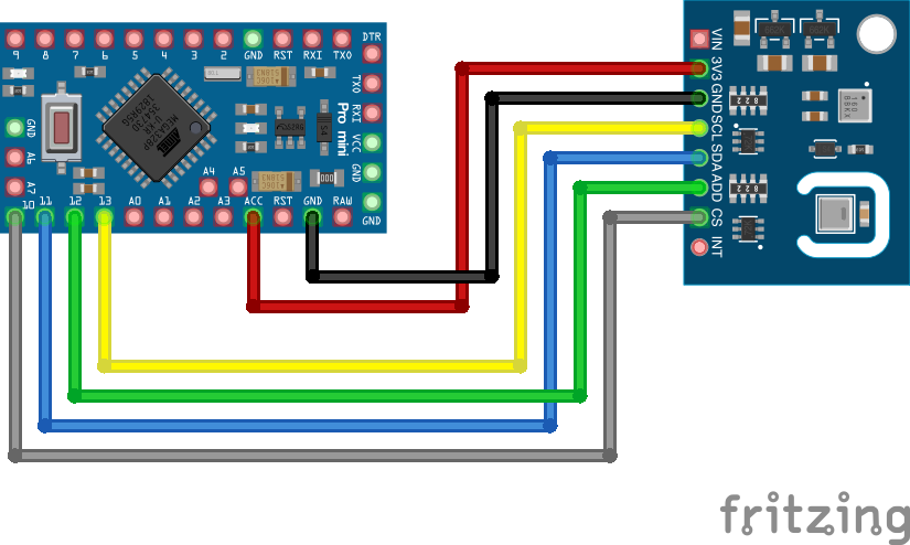
Arduino Pro Mini / ENS160 SPI Electrical Circuits
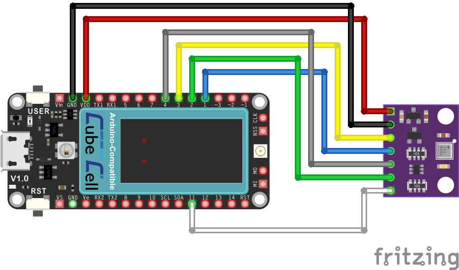
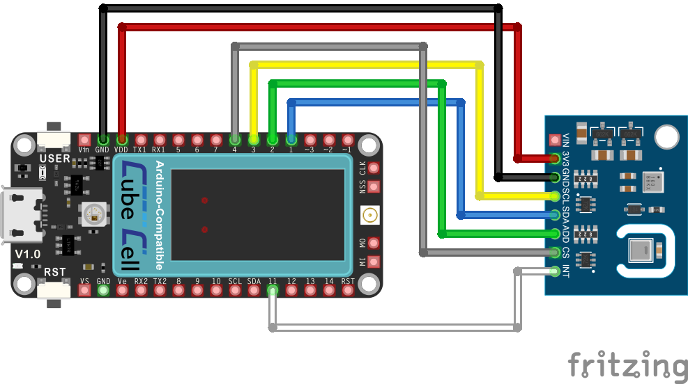
CubeCell Plus / ENS160 SPI Electrical Circuits
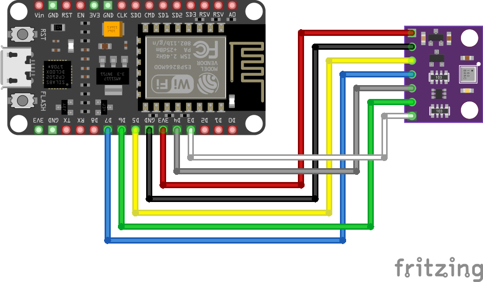
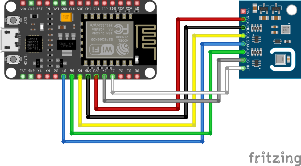
NodeMCU / ENS160 SPI Electrical Circuits
Pin Configurations
| Arduino Pro Mini | CubeCell Plus | NodeMCU | ENS160 | ENS160 + AHT21 |
|---|---|---|---|---|
| VIN | ||||
| ACC | VDD | 3V3 | 3V3 | 3V3 | GND | GND | GND | GND | GND |
| 13 | SCK1 (GPIO3) | D5 | SCL (SCK) | SCL (SCK) |
| 11 | MOSI1 (GPIO1) | D7 | SDA (MOSI) | SDA (MOSI) |
| 10 | GPIO12 | D4 | CS | CS |
| 12 | MISO1 (GPIO2) | D6 | ADD (MISO) | ADD (MISO) |
| A0 | GPIO11 | D3 | INT | INT |
Note that only the ENS160 sensor is accessible via the SPI interfacce. The AHT21 temperature sensor, on the ENS160+AHT21 module, can only be used in an I2C configuration.
Software
When using the I2C interface, the ENS160 sensor on the [purple] ENS160-only board defaults to I2C address 0x52 on start-up while that on the ENS160+AHT21 board defaults to I2C address 0x53, with the AHT21 sensor on the latter using the I2C address 0x38. The default I2C address of the ENS160 sensor on either board can nonetheless be overridden by holding the ADD pin to GND to use 0x52 or VCC to use 0x53.
I tested both boards with three ENS160 libraries (AdaFruit, DFRobot and SparkFun) available through the Arduino IDE Library Manager but the only one that actually worked 'out of the box' with either of boards I was using was the DFRobot DFRobot_ENS160 library. Conveniently, DFRobot also had a library, DFRobot_AHT20, that could be used with the AHT21 sensor and which I reasoned might also, coming from the same developer, minimise the potential for any library conflicts when using both.
The original DFRobot_ENS160 library was nonetheless modified to add a method that allowed the 'dynamic' setting of the I2C address being used to communicate with a sensor, thus allowing me to use the same sketch with either ENS160 module. This modified version of the library is available from my GitHub repo.
The following sketch was used to run the sensors during their initial burn-in phase and more generally test their operational characteristics.
|
While the [purple] ENS160-only board was recognised and successfully initialised when connected via either the I2C or SPI bus, I could never get it to return any data. Following comments in various forum posts on the subject, I tried using different power sources and even leaving the module running for 24 hours in case it only became active after the recommended burn-in period, all without success. Using essentially the same configurations, the ENS160+AHT21 board ran, without any problems, from the outset.
Calibration
Having now worked with the three different air quality sensors, CCS811, ENS160 and MQ-135, there is clearly a need for some level of calibration. Out of the box, the three sensors give wildly different readings and they certainly need the recommended burn-in period (48hrs) before measurements from individual sensors settle down and become consistent. After the burn-in period, the relationship between eCO2 and TVOC measurements on the individual CS811 and ENS160 sensors are at least consistent, but the absolute measurements on the CCS811 (eCO2 1980 ppm) are still more than double those measured with the ENS160 (eCO2 790 ppm) in my current test environment, and even the latter is higher than I'd expect it to be. There's still a bit of work to do here...
Sensor Readings
Refer to the ENS160 datasheet for a full description of the capabilities and usage of the sensor.
Start-Up and Response Times
The following details, taken directly from the ENS160 datasheet, are of particular interest in relation to taking measurements with the sensor.
| State | Max Time |
|---|---|
| Initial Start-Up | 1 hour |
| Warm-Up | 3 minutes |
| Immediate Response | 1 second |
Initial Start-Up is the time the ENS160 needs after its first ever power-on before it will return reasonable air quality readings. It is recommended that a new sensor be powered on and left running for at leat 24 hours before actually being used. Changes in raw resistance signals and sensitivities will be greatest in the first 48 hours of operation.
After the initial power-up, a conditioning or warm-up period is also generally recommended to allow the sensor to stabilise, after idle periods or power-off, before making measurements.
OPMODE
The ENS160 sensor can operate in three modes: Standard [Gas Sensing Mode], IDLE (low power) or DEEP SLEEP (low-power standby). It would seem that the normal mode of operation is for the sensor to sit in IDLE mode until it is required to make a reading, when it would be switched to STANDARD mode. Given that, in the present case, the sensor is intended to be part of a battery-powered configuration, it will likely spend most of its time in either IDLE or DEEP SLEEP mode. I am, however, yet to explore these options and any implications they might have in the way a Node's hardware/software environment needs to be managed.
Interrupts
While some sensors provide the ability to configure the generation of an interrupt when a previously set threshold is exceeded, the ENS160 interrupt model is simply one where an interrupt is generated when new data is available. This may or may not be of any interest, depending on how the sensor responds to being brought out of DEEP SLEEP when the Node cycles through a reporting period, but I am yet to explore this option.