MQ-135 Air Quality Sensor

MQ-135 Air Quality Sensor
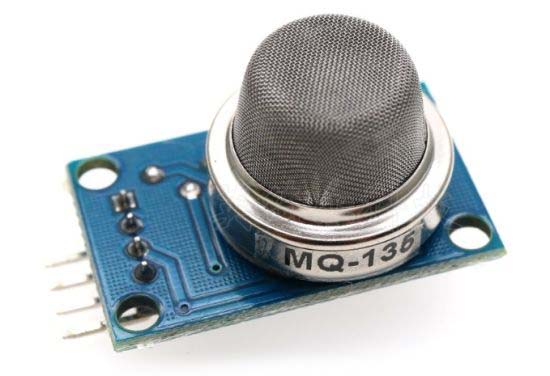
This section deals with the configuration of the MQ-135 air quality sensor.

Application

The wording used in describing the capabilities of the MQ-135 sensor, in both the MQ-135 datasheet and in various examples of its use, is a little misleading in that it suggests that the sensor is capable measuring the concentration of specific pollutants, CO2 or NH3 for example, in the air. In fact, it is not capable of identifying any specific gas or pollutant, it simply provides a measurement, as the name of the sensor implies, of air 'quality', that being the presence or otherwise of any of the gases or pollutants noted (CO2, NH3, NOx, alcohol, benzene, 'smoke' etc.). The ultimate sensor reading can then be used to calculate the 'equivalent' concentration of a particular gas, e.g. equivalent CO2 (eCO2) concentration, which would be the CO2 concentration if the reading were due entirely to the presence of CO2 and no other gas to which the MQ-135 was sensitive. Exactly the same reading could be presented as acetone-equivalents or ammonia-equivalents, even though there may be no acetone (H2CO) or ammonia (NH3), or even CO2 for that matter, present in the measured sample.

Either way, in deploying the sensor, one establishes a reading that is consistent with some benchmark concentration of the measured gas(es), so-called 'clean air', then measures the deviation from this state, which will be proportional to the change in the total concentration of all of the relevant pollutants. Any suggestion that the sensor is measuring the concentration of something more specific, like only CO2 or NH3 for example, is not correct unless, of course, that gas is the only pollutant present, which will not usually be the case.

Regardless, recent investigations seem to suggest that the ESN160 air quality sensor might be a better option for my immediate application, my local weather station.

Configuration

Just a few links and comments for the time being. When I get back to this sensor, I will provide more detail on the configuration I ultimately use.

Circuit Digest

Olimex Technical Data

Arduino Forum Waveshare Discussion (Circuit layout, component functions — mainly what's NOT required for analog readings, like almost all the extra stuff is there is for the digital output signal)

Teach Me Micro (Formulae, schematic etc.)

The Engineering Projects (Comments on getting the same result, just with a different scale, nominating different gases as the one measured)

Medium ()

Bobbo117 on GitHub, good run through the calibration process

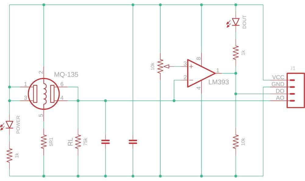
As best I can work out, the schematic for the MQ-135 module that I have is as illustrated below.
MQ-135 Module Schematic

MQ-135 Module Schematic

Note, in particular, that the only component, other than the sensor itself, that has any bearing on the actual sensor measurements is the load resistor, RL, which will effectively set the sensitivity of the sensor. The LM393 comparator and associated circuitry is only used to generate the digital output signal.

Much is made in posts discussing this sensor about the inappropriate choice of the value of the load resistor configured on some of these modules as supplied. The recommended range for the load resistor, depending on the application (i.e. the gases of most interest), seems to be 10kΩ~47kΩ with the Olimex MQ-135 datasheet recommending a value of 20kΩ. In the present case, a 75kΩ load resistor, which measures an actual 74.2kΩ, has been configured.

While most sources, including datasheets from two different manufacturers, suggest that the MQ-135 sensor requires a 5V supply voltage, I found one source that indicated that the supply voltage could be in the range 2.5~5V. I did try to run the sensor at 3.3V, but the behaviour was unusual and after 30 min its readings were well beyond those of the other two sensors and still steadily increasing. On reverting to the 5V supply, after a bit of a spike, readings steadily returned to normal.

Hardware
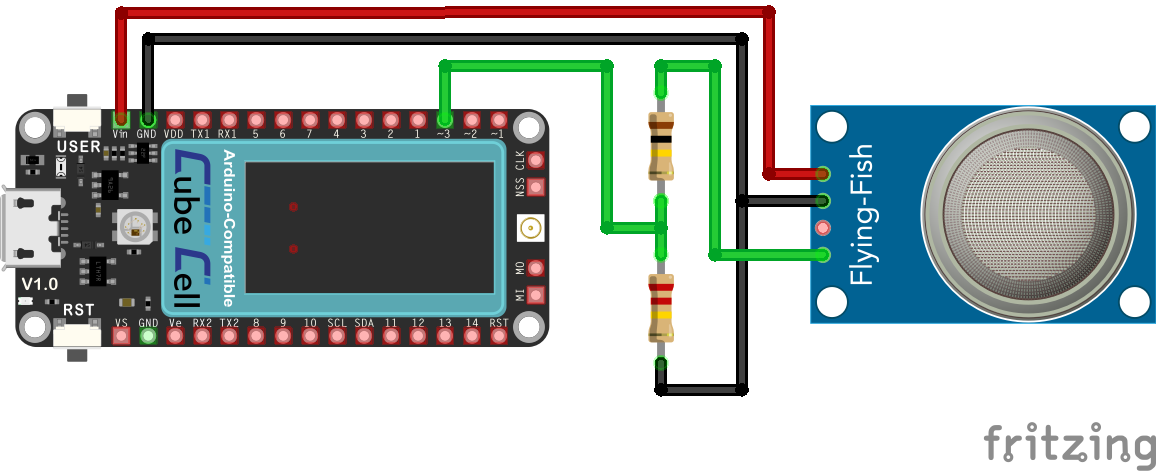
CubeCell / MQ-135 Hardware Configuration

CubeCell Plus / MQ-135 Electrical Circuit
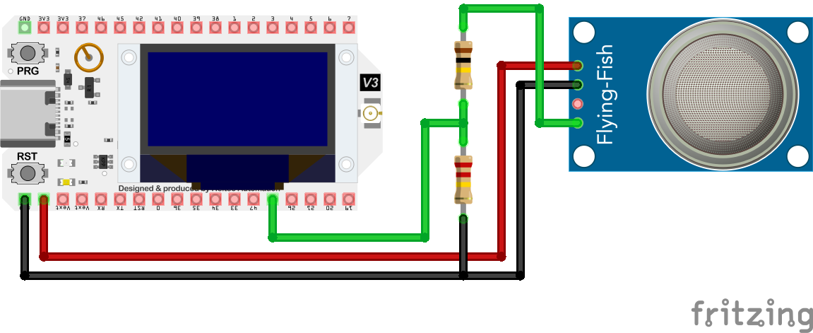
WiFi LoRa 32 (V3) / MQ-135 Hardware Configuration

WiFi LoRa 32 (V3) / MQ-135 Electrical Circuit
Pin Configurations
CubeCell Plus WiFi LoRa 32 (V3) MQ-135
Vin 5V VCC
GND GND GND
D0
ADC3 GPIO48 A0

Software

NOTE : The MQ135 library loaded through the Arduino Library Manager is configured for a 10-bit ADC. To function correctly with the CubeCell Plus 12-bit ADCs, the MQ135.cpp file must be modified at line 68 to specify the increased range (4095).

I would have thought the configuration of any voltage divider required to bring the input signal within the range of the target ADC. These considerations will generally be processor-dependent.

The following sketch is a slightly modified version of the sketch referenced therein. It includes the functionality to display the results on the CubeCell Plus onboard display.


CubeCell Plus / MQ-135
#define VERSION "MQ135_Air_Quality_2025_0916"

/*
   IMPORTANT - read project description at
   https://github.com/Bobbo117/MQ135-Air-Quality-Sensor

  This software incorporates the MQ135 library to do perform two functions:
  1. When the #define CALIBRATE statement is active, calibarate the MQ135 sensor 
  2. When the #define CALIBRATE statement is inactive, read the MQ135 sensor and report the CO2 ppm data on the following platforms:
  
    computer monitor via USB connection
    OLED display via I2C connection

*/    
//////////////////////////////////////////////////////////////  
//*******         Compile-time Options           ***********//
//        (Disable unwanted options with leading //)
//////////////////////////////////////////////////////////////

#define CALIBRATE_         // Comment out if not in calibration mode

//////////////////////////////////////////////////////////////  
//*******         Compile-time Parameters           ***********//
// IMPORTANT - read project description at
// https://github.com/Bobbo117/MQ135-Air-Quality-Sensor
//////////////////////////////////////////////////////////////

#define PIN_MQ135 ADC3    // ADC3 pin on the CubeCell Plus, which connects to the analog output of the sesor. 
#define RZERO 310.0       // Measured resistance from calibration run
#define RLOAD 74.2        // Measured resistance Kohms pin module A0 to GND with power off

//////////////////////////////////////////////////////////////  
//*******         Libraries          ***********//
// Use the Arduino Library Manager to install libraries for selected compile-time options 
// 
//////////////////////////////////////////////////////////////

//***Sensor library
#include "MQ135.h"        // <-- from Arduino Library Manager
MQ135 gasSensor(PIN_MQ135, RZERO, RLOAD);

#include <HT_SH1107Wire.h>      // CubeCell Plus display library
SH1107Wire  boardDisplay(0x3c, 500000, SDA, SCL, GEOMETRY_128_64, GPIO10); // addr, freq, sda, scl, resolution, rst

//***Variable Definitions

  unsigned long reportPeriod_msec = 15000;        // Report period in msec
  float ppmArray[8];                             // array used to store and calculate rolling average of ppm data
  int ppmArrayLength = 8;                        // array length 
  int validArrayData = 0;                        // number of entries in the array which are valid data for use in rolling average
  
//   ***********************
//   **  setup()  **
//   ***********************

void setup() {
  Serial.begin(115200);
  ppmArray[0]=1;                                      // ppmArray[0] is index pointing to first data location

  pinMode(Vext, OUTPUT);    // Sensor power
  digitalWrite(Vext, LOW);  // Activate Vext (we're really writing to Vext_Ctrl here)
  pinMode(ADC3, INPUT);     // MQ-135 anlaog input

  boardDisplay.init();
  boardDisplay.setFont(ArialMT_Plain_10);
  boardDisplay.screenRotate(ANGLE_180_DEGREE);
    
  boardDisplay.clear();
  boardDisplay.setFont(ArialMT_Plain_10);
  boardDisplay.setTextAlignment(TEXT_ALIGN_LEFT);
  boardDisplay.drawString(5,0,"MQ-135 Sensor");
  boardDisplay.display();
  delay(1000);
}
 
//   ***********************
//   **  loop()  **
//   ***********************

void loop() {            
  //***print to Serial Monitor
  #ifdef CALIBRATE_
    //****Read sensor resistance
    float value = gasSensor.getRZero();
    Serial.print("R Zero Ohms: ");  
    Serial.println(value);
  #else
     //****Read air quality sensor
    float value = gasSensor.getPPM();
    Serial.print("Air Quality: "); 
    Serial.println(value);
  #endif

  //***Store in array
  ppmArray[int(ppmArray[0])]=value;
  //Serial.print(ppmArray[0]); Serial.print(": ");Serial.println(ppmArray[int(ppmArray[0])]);
  ppmArray[0]++;
  if (int(ppmArray[0]) > ppmArrayLength-1) {
    ppmArray[0]=1;
  }  
  if (validArrayData < ppmArrayLength-1) {
    validArrayData ++;
  }
  
  //***Compute rolling average
  float total = 0;
  for (int i=1; i< validArrayData+1; i++) {
    total = total + ppmArray[i];   
  }
  float avg = total/(validArrayData);   
  Serial.print("Rolling Average ");Serial.print(validArrayData); Serial.print(": ");Serial.println(avg);
  
  //****Display AQI value on OLED
  boardDisplay.clear();
  boardDisplay.setFont(ArialMT_Plain_10);
  boardDisplay.setTextAlignment(TEXT_ALIGN_LEFT);
  #ifdef CALIBRATE_
    boardDisplay.drawString(5,10,"Calibration");

    boardDisplay.setTextAlignment(TEXT_ALIGN_RIGHT);
    boardDisplay.drawString(45,20,"R0");
    boardDisplay.drawString(45,30,"Count");
    boardDisplay.drawString(45,40,"Average");

    boardDisplay.setTextAlignment(TEXT_ALIGN_LEFT);
    boardDisplay.drawString(55,20,String(value) + "kOhms");
    boardDisplay.drawString(55,30,String(validArrayData));
    boardDisplay.drawString(55,40,String(avg) + "kOhms");
  #else
    boardDisplay.drawString(5,10,"Air Quality Index");

    boardDisplay.setTextAlignment(TEXT_ALIGN_RIGHT);
    boardDisplay.drawString(45,20,"R0");
    boardDisplay.drawString(45,30,"Count");
    boardDisplay.drawString(45,40,"Average");

    boardDisplay.setTextAlignment(TEXT_ALIGN_LEFT);
    boardDisplay.drawString(55,20,String(int(value)) + "ppm");
    boardDisplay.drawString(55,30,String(validArrayData));
    boardDisplay.drawString(55,40,String(int(avg)) + "ppm");
  #endif   
  boardDisplay.display();
  
  //****Pause to throttle data rate.
  Serial.print(reportPeriod_msec/1000);Serial.println(" second pause..");Serial.println("");
  delay(reportPeriod_msec);
}
Calibration

Since this sensor is sensitive to a range of gases, it is important that it be calibrated, in the environment in which is to operate, to the expected background gas composition. In the present case, this will simply be the local atmospheric conditions and the sensor will simply be measuring variations from these background conditions.

The procedure followed to calibrate the MQ-135 sensor is described in the README.md file in the Bobbo117/MQ135-Air-Quality-Sensor repo on GitHub.

Further details pending

03-09-2026